Update 05/16:
Did some building and roasted two electrical lighters. Am kinda at the point where I'll just want to build my own, though there being some tutorials on the web, they are sadly not including any way of calculating and designing one for yourself.
Does any of you can point me in the right direction? As much as I know is, that I'll need a DC-AC inverter and some high step up transformer.
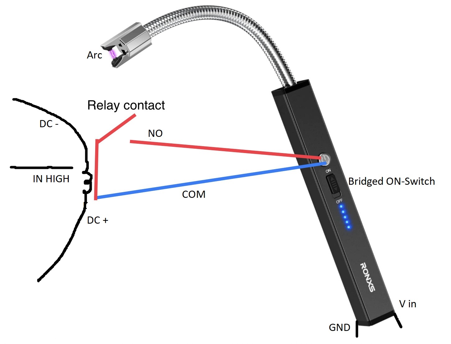
EDIT: Fixed Diagram Relay labeling
Hi folks,
first time posting here and tinkering with anything Ardu.
Please have a quick look, if you spot anything wrong or can give some advice.
Notes & Questions:
- Will the Nano be fine being parallel to all and being powered via 5 V i/o?
- Is it wise to connect the electric lighter, which is likely to be powered by a 1s LiPo (3.7V), directly to the 5V?
- Adding a parallel load resistance, if the quiescent current isn't enough to prevent the powerbank's auto shutdown.
- Would there be enough room to add an additional led strip and a sound module?
Enough babbling, here's the diagram:

EDIT: Fixed Relay NC to NO
Button 1 triggers the servo and arc lighter via GPIO pins
Button 1 triggers the servo via GPIO pin
The specs:
Arduino Nano
Powerbank: Intenso Powerbank XS 5000 (no link, limited to 2)
Output
- USB-A + USB-C
- 5000 mAh: 5V - 2.1A total
Input
- microUSB + USB-C
- 5000 mAh: 5V - 2.1A
Arc lighter: RONXS Lighter, USB Rechargeable
Black Box, Probably driven by 1s LiPo (3,7 V)
Servo: Miuzei 9G Micro: Servo (no link, limited to 2)
- 9g Mini Servo : The micro servo is tiny and light - equipped with metal gear. high output, high quality and high cost performance.
- Size: 23mm12.2mm29mm(LWH) with 250mm cable length. Weight: 9G*5pcs.
- Operating Voltage: 4.8V~6.0V, Control Angle: 180°(500~2500usec),
- Operating Temperature:-25℃~55℃
- Amplifier type: Analog control, Dead zone setting: 8 usec. Operating speed: 0.09sec/60° (4.8V); 0.08sec/60° (6V).
Relay: 1-channel relay module, 5V, with optocoupler, supports high and low level trigger, for Arduino (GER Amazon Link, specs are translated below)
- Type: 1-channel relay module with optocoupler and high or low level control
- Working voltage: 5V
- Module Size: 50x26x18.5mm / 1.97x1.02x0.73 inch (LWH)
- Quiescent current: 5mA
- Maximum current: 190mA
- Tripping current: 2-4mA
- Trigger Voltage (Low): 0-1.5V
- Trigger voltage (high): 2.5-5V
- Power indicator: Green
- Relay Status Indicator: Red
- 4 mounting screw holes, bore 3.1mm/0.12in, pitch 44.5x20.5mm/1.75x0.81in
- Delivery content:
- 6 x 1-channel relay module
- Module interface:
- DC+: connected to the positive pole of the power supply
- DC-: connected to the negative pole of the power supply
- IN: can control the relay to pull the level high or low
- Relay output:
- NO: The relay is normally open, the relay is stuck before suction, and the short circuit is connected to COM after suction.
- COM: Common relay interface.
- NC: The relay normally closes the interface, and the relay is short-circuited before the intake is closed.
- High and low trigger selection:
- -It is a low level trigger when the jumper is connected to the LOW pin.
-
- It is a high level trigger when the jumper is connected to the HIGH pin.