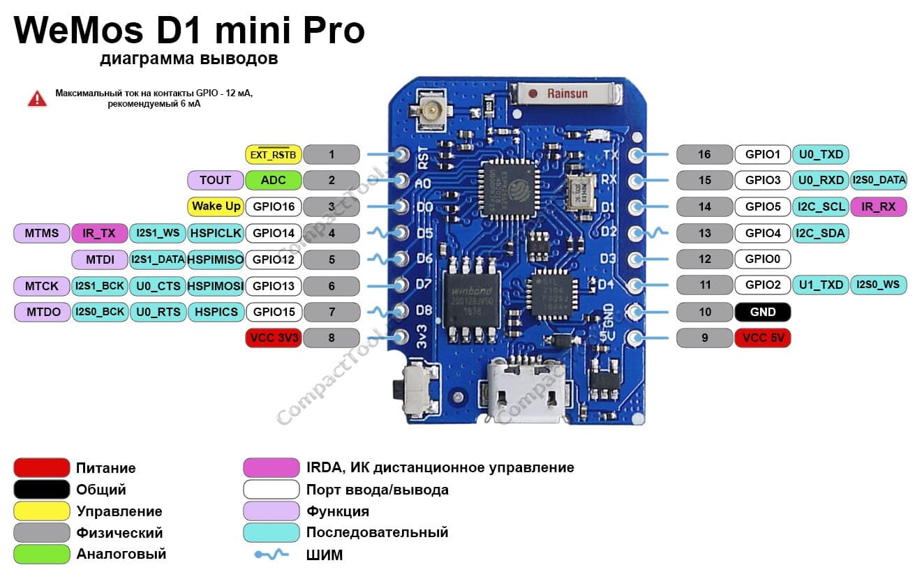
I just got two D1 MINI PRO, but the upload is not working.
I found, that the communication chip is a CH9102. The driver is installed an in the device manager I can see, that the connection to the Mini Pro is established (after connection the Mini Pro the COM-Port is available).
When I try to upload a program with my Arduino IDE the connection is not working
esptool.py v3.0
Serial port COM20
Connecting........_____....._____....._____....._____....._____....._____.....____Traceback (most recent call last):
  File "C:\Users\HJ\AppData\Local\Arduino15\packages\esp8266\hardware\esp8266\3.0.2/tools/upload.py", line 66, in <module>
    esptool.main(cmdline)
  File "C:/Users/HJ/AppData/Local/Arduino15/packages/esp8266/hardware/esp8266/3.0.2/tools/esptool\esptool.py", line 3552, in main
    esp.connect(args.before, args.connect_attempts)
  File "C:/Users/HJ/AppData/Local/Arduino15/packages/esp8266/hardware/esp8266/3.0.2/tools/esptool\esptool.py", line 529, in connect
    raise FatalError('Failed to connect to %s: %s' % (self.CHIP_NAME, last_error))
esptool.FatalError: Failed to connect to ESP8266: Timed out waiting for packet header
esptool.FatalError: Failed to connect to ESP8266: Timed out waiting for packet header
Then I changed to the serial monitor. I can see, that the Mini Pro is sending data after pressing the reset button. I got a readable output when I selected the baud rate 74880.
On my computer I found boards.txt under C:\Users\HJ\AppData\Local\Arduino15\packages\esp8266\hardware\esp8266\3.0.2.
In the section d1_mini_pro.menu.baud I added two lines:
post a picture of your ESP8266 D1 mini pro.
On some boards there is no capacitor between Enable-pin and ground
nodeMCU-boards all have a second button that connects EN to ground when pressed
the ESP8266 D1 mini (without pro) has such a capacitor and has the ESP8266 soldered as a small PCB where the EN-input is accessible.
Be the change you want to see in the world
best regards Stefan
To enable ESP8266 firmware flashing GPIO0 pin must be pulled low before the device is reset. Conversely, for a normal boot, GPIO0 must be pulled high or floating.
thanks for your hint. I had also a Mini Pro with a SIL2104 and in this case, the upload is working.
So, I checked the wiring of the board. For me the layout of the PCB is 99% the same (as far as I can see). The 6-pin chip between the processor and the USB-chip is a transistor array. These transistors handle the reset and the GPIO0 handling based on the DTR and RTS signal. I found, that in both devices the wiring is the same.
Had you ever found a ESP8266 device, where the bootloader is not working and need to be re programmed? Currently I think that this might be the problem.
AVR microcontrollers are programmed (aka flashed, or uploaded) using ISP (in-system programming) over SPI. They don't support programming over UART out of the box. To receive new firmware over the serial port, a bootloader is used. It is a piece of software that receives data from the UART and writes it to flash, overwriting the previous firmware.
The situation on an ESP8266 is completely different. Whereas on an AVR, ISP is the default method to flash new firmware, on the ESP8266, it is UART flashing. The ESP8266 already has a system built-in for UART flashing (just like an AVR has a system for ISP flashing), so you don't need to flash a software UART bootloader.
There is no ISP system inside of the ESP8266, so trying to do ISP on the HSPI port won't flash anything.
google translated
AVR-Mikrocontroller werden mit ISP (In-System-Programmierung) über SPI programmiert (auch bekannt als geflasht oder hochgeladen). Sie unterstützen keine Programmierung über UART von Haus aus. Um neue Firmware über die serielle Schnittstelle zu erhalten, wird ein Bootloader verwendet. Es ist eine Software, die Daten vom UART empfängt und in den Flash schreibt, wobei die vorherige Firmware überschrieben wird.
Die Situation auf einem ESP8266 ist völlig anders. Während auf einem AVR ISP die Standardmethode zum Flashen neuer Firmware ist, ist es auf dem ESP8266 das UART-Flashen. Der ESP8266 verfügt bereits über ein integriertes System für UART-Flashing (so wie ein AVR über ein System für ISP-Flashing verfügt), sodass Sie keinen Software-UART-Bootloader flashen müssen.
Es gibt kein ISP-System im ESP8266, daher wird der Versuch, ISP auf dem HSPI-Port auszuführen, nichts flashen.