You can assume that all components that have a completed current path flow will consume power. The circuit shown in post 15 will draw power when the MCU is sleeping. If the sensor has a connection to power and ground and does not have a deep sleep mode, that the sensor can be placed into, then the sensors power draw is not reduced. Also, powering up the sensors may be more costly than keeping them running all the time.
Does anyone have any feedback regarding this?
Should I look for a diode with a higher Vf so that if my devices consume less than i.e. .5 amps the Vf will be sufficient at that level to keep the voltage to the capacitor under/near 6V?
Hi,
QUESTION: Are you going to use a shunt or other type regualtor between the PV and your supercaps?
If YES, then stop over thinking the situation, this is where you need to bite the bullet, get some parts together and prototype, check ALL your assumptions/queries.
The regulator will prevent the caps from over charging, that is what its designed to do.
If NO, then not having any regulation is a bad idea when considering how close your PV performance is to driving the caps outside their specs.
Tom... ![]()
![]()
![]()
![]()
PS. I hope you are not expecting after all this "research", that you can just build it and it will instantly work to specs?
Yes, and this is starting to get tiresome. You must not rely on the forward voltage drop to protect your supercap. You've already been told what to do. Shunt excess voltage so that the voltage across the supercap cannot exceed its rated voltage under any circumstances.
OR: use a buck/boost regulator, set to a safe output voltage.
Shunt regulating a 1.6A solar panel for a tiny 5F supercap seems a bit silly (needs a heatsink).
A 50mA panel should be more than enough for that size cap.
Leo..
I think you are right. I was really just emphasising the importance of not exceeding the cap's rated voltage and the folly of relying on forward voltage drops, etc.
A shunt regulator makes use of the fact that a solar panel is mainly a current source.
That means you can safely short-circuit a solar panel. Problem is that a shunt regulator converts all solar power into heat when battery/cap is charged. And that's a problem when your panel is too big.
For a 5.5volt (2-cell) supercap, you should have used a 9volt solar panel (+ shunt regulator).
The 5.5volt/6volt panel you have is a good choice for a 4.2volt LiPo cell (with series regulation).
~About 50% panel over-voltage ensures some charging on overcast days.
I still doubt you get much joy from a tiny 5F cap with the hardware you're planning to use.
Since you have a large 6volt panel, I would dump the supercap and go for LiPo.
Leo..
Thanks all for various solutions
The shunt solution is great except I don't know how to wire it and most of the ones I'm finding don't have the current output capacity of the panel. I'll research it some more.
The zener diode and/or schottky diode solution also has the issue of Vf varying based on current draw.
The step down boost converter issue here is low light / shaded sky conditions won't allow for lower voltage power to go through.
The LDO voltage regulator (here I've seen even low voltages allowed to pass through with a max output of 6V, but current limitations occur again)
I found my 5V panel based on past projects and test setups.
5V, 200 mA, Voc 6V
For now this is my planned setup and as soon as parts arrive I will test this out.

Have you calculated how long the panel will take to charge the capacitor?
its rated at 1.6A so you can expect 1.2A optimally oriented in bright sunlight
or around 0.5A on an average day.
Your 5F cap can store (Q =C V =I t) 5 * 5 =25 coulombs = 0.5A * 50 seconds.
Which is why cheap solar lights use batteries.
Thanks for the time to charge calculation, I was getting confused by the 63% charge (τ=RC) formula.
In that case I didn't use a resistor in place like I see in a lot of examples online, but I used the internal resistance of the supercapacitor.
I've attached a spreadsheet of the latest calculations so others can use it/build upon it, etc..
Used the 5V, 200 mA solar panel for reference.
Using your calculations with full 5V, 0.2A it's around 138 seconds.

Solar Panel Charging Super Capacitor and Powering MCU Calculations, R2.zip (47.2 KB)
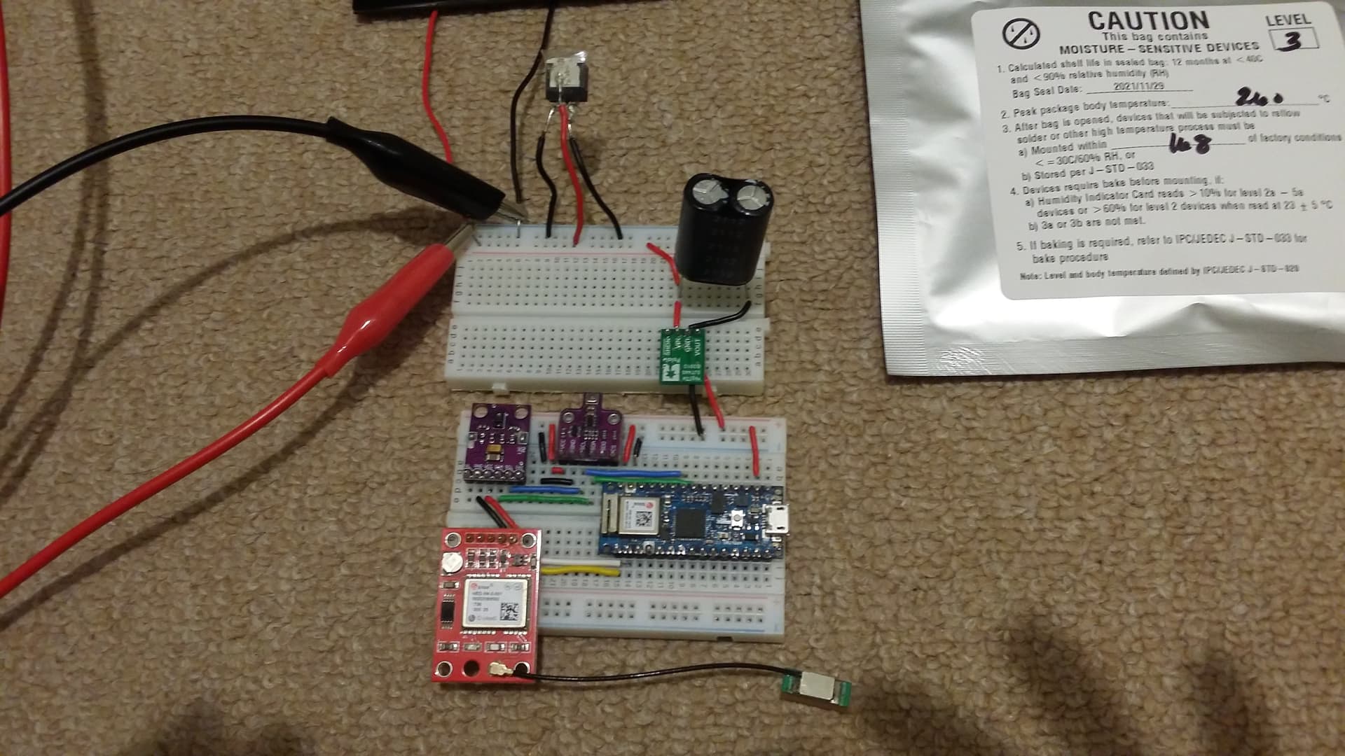
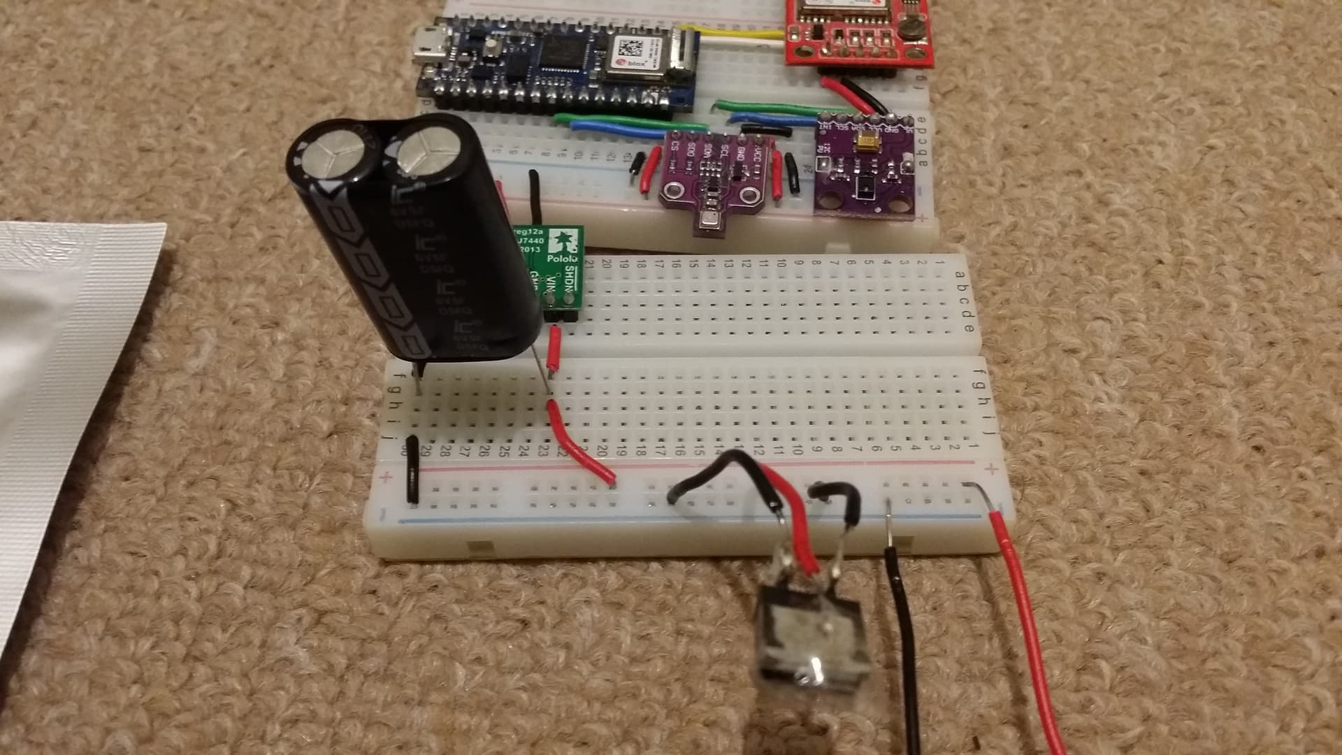
Going to try this out tomorrow during day time but here is the setup for reference:
I'm tempted to test the setup in the night by powering up the supercapacitor with the smart bypass diode in place using a DC power supply but I am worried since I don't have a resistor in place to limit current flow to it.
The cathode side of the SM74611 Smart Bypass Diode was a pain to solder even with rosin flux core solder. After several failed attempts, I kept the connection together with some tape.
SM74611 Smart Bypass Diode datasheet (Rev. B)
See page 3.
The silver package has ESD caution notice for the part, and some humidity and bake before mounting for reflow soldering, etc instructions.
Here is a CAD model for sizing reference:
SM74611, Smart Bypass Diode
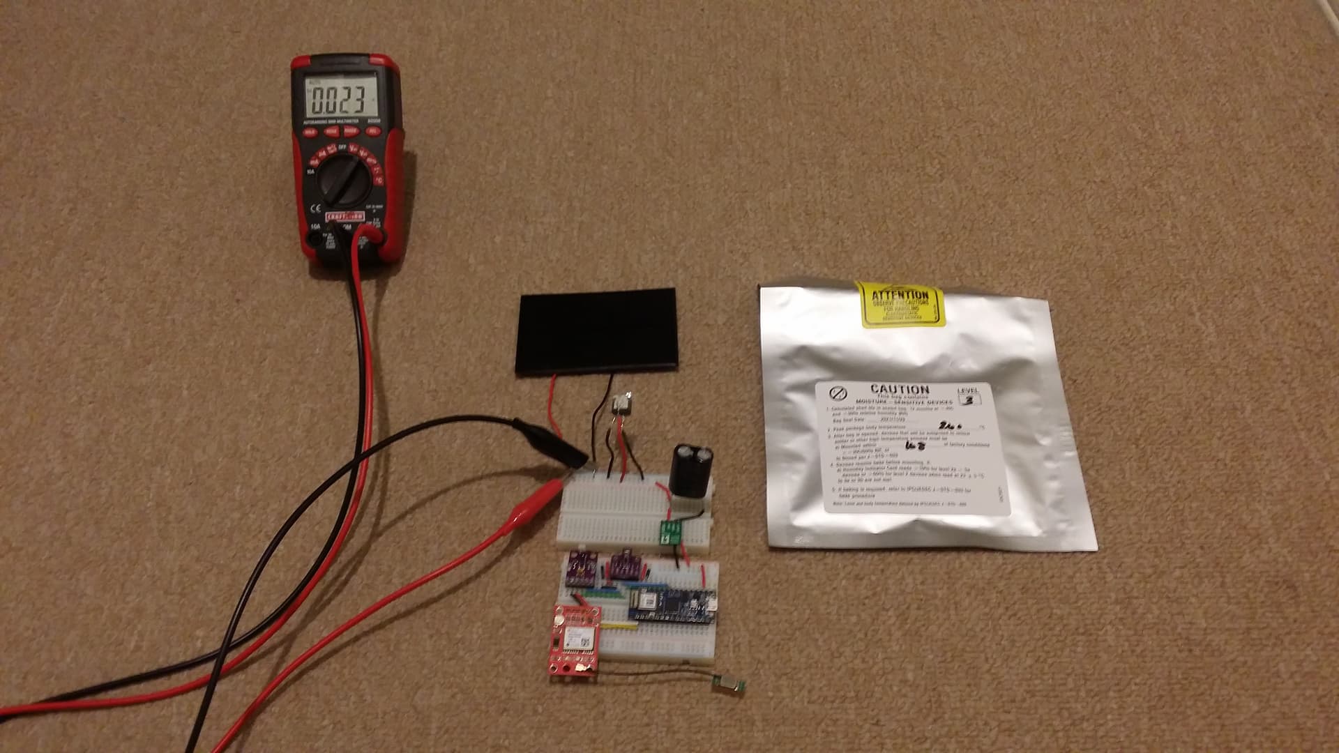
Update, so even though the panel is rated at 5V, I'm still getting 5.7 volts into the supercapacitor without any load on it. With load, it sits at around 5.3 volts.
FYI for this particular setup I used my DC power supply to test the limits of the Pololu U1V11F3.
The highest voltage output I set my DC supply to was 5.8 volts.
The circuit appeared to have been consuming 130 mA on average at that voltage based on the DC power supply display.
Wawa made a good point about the buck boost regulator consuming power, Pololu U1V11F3.
It's 1 mA.
Once the supercapacitor reaches around 0.4V, I had to constantly disconnect the converter to allow the supercapacitor to be charged to a higher voltage. The regulator has a shutdown feature which I still have to learn how to use.
With no load:

With load:

The purpose of a smart bypass diode is to provide a path for current if one or more solar panels in an array are shaded. Why dont you use a conventional silicon diode that will drop the unwanted 0.7V?
So why not put one in? otherwise sooner or later I'll bet your supercapacitor will fail supercapacitorspectacularly.
The smart bypass diode has some other advantages too.
It also will give others some future proofing if they go with higher voltage solar panels and add more peripherals to their setup. I'm planning on adding more later.
DC Reverse voltage 30V Maximum
Forward current 8 A Typical 15 A Maximum
Forward voltage = 26 mV ( At 8 A, T = 25°C )
Reverse leakage current = 0.3 µA (28 V Reverse Voltage, TJ = 25°C)
3.3 µA (28 V Reverse Voltage, TJ = 125°C)
I figured regardless of what voltage I choose, the 0.7v voltage drop of the zener diode (i.e. post no. 1, Nick gammon's example of using 1N752 zener diode, Barebones Atmel 328p Solar powered Arduino is not allowing for full collection of my solar panel's power output. So on overcast days I instead of 5V I could be getting 4.3 volts, etc....
So I was trying to drop losses in efficiency with the smart bypass diode.
Also the leakage current from the super capacitor to the solar panels was a concern.
With the smart bypass diode it's 3.3 uA at 28V.
With the zener diode it becomes higher at lower voltages correct?
Then there is the issue of how much current/power the zener diode can handle.
1N752 specs
It seems for the 5.6V zener diode it's 60 mA.
1N746A its 3.3V and 110 mA
Based on the super capacitor datasheets the max currents they can handle are 8 amps, so even if I used the 6V, 1.6 amps (won't get this max value likely). I won't really be stressing out the supercapacitor correct?, so that's why I didn't add a resistor (plus they have their own wattage ratings too of what they can handle).
Plan is to build a weather monitor and send values to the Arduino IoT cloud, it can remain fully active at day time and send periodic updates during night time and do deep sleeping in between those periods during night time.
Right now with my DC power supply, I'm getting.
3.3V and 0.118 A (without WiFi being on and sending data to cloud)
With these peripherals (getting these currents from the data sheets, i.e. continuous power mode,etc):
ADPS 9960 (.79 mA ??, 12.5-100 mA led drive current - gesture detection)
(i'm using it to detect color/ ambient light to initiate deep sleep mode, etc...)
Neo 6m gps (47 mA)
BME680 (18 mA)
Want to add an encoder to for wind speed detection (one I selected =<80 mA max current consumption, 40mA load current)
Datasheets for peripherals:
NEO6M GPS
BME680
Encoder for wind speed
ADPS-9960

If its to limit PV current, don't worry, look at the short circuit current of your PV, the current will not get anywhere near that level.
Remember a PV cell is a current source NOT a voltage source.
Tom.. ![]()
![]()
![]()
![]()
Oh no it was to limit current to the supercapacitor, I don't think it would draw 1.6 amps into itself even though my current setup is consuming 3.3v, ~120 mA. Even if it does the 6V supercapacitor data sheet says the max amps it can handle is 8 amps.
I just noticed this common setup of using a diode, a resistor in between their solar panel setup and the supercapacitor online in different google searches.
I don't understand this. If you had the same size solar panel either way, but one organized as a 5V panel and the other as a 9V panel, wouldn't you get the same charging power under a given cloudy condition with either panel? I've never really understood solar panels, so my apologies if this is a dumb question.
A solar panel should have a diode between the solar panel + and the load. A solar panel will draw current from the battery when the sun is down. Reverse current flow in a solar panel can harm the individual solar cells in the panel.
A solar panel is mainly a current source, so you can safely short circuit a solar panel.
Or use a shunt regulator across the panel (that shorts excess voltage/current).
Solar cells output less voltage on dark days. Some types are worse than others.
Thin film is better on dark days (Nick Gammon used it), but harder to get at the right voltage.
Solar lights with glass panels use thin film (smooth brown coloured cells).
If you don't use a (power-hungry) boost converter, then you need a higher solar voltage for those dark days. That also means you must use a (shunt) regulator, to protect the cap from over-voltage.
A (shunt) regulator also means the cap (or battery) can now be fully charged under any conditions.
Yes, you need a back-flow diode between panel and cap, because the panel becomes a load when the sun goes down. If you use a panel with slightly higher voltage, then a more common Schottky diode (1N5819) is fine, instead of that lossless diode, which might leak more at night.
Sleep current and other leakage currents are the main enemies when bridging the night.
A supercap itself also leaks significantly, usually about 1-5 uA per Farad.
Are you sure a supercap is the best choice. A 1Ah LiFePo4 setup could be much easier for a weather station with WiFi. That type of battery outputs a fairly constant 3.3volt that you can directly use to power a 3.3volt Arduino. Try to find them in a solar light replacement battery store.
Oh, and the only dumb thing is to not ask questions.
Leo..
A 12V solar panel on a cloudy day will deliver more current than a 5V solar panel on a cloudy day. A 100W 12V solar panel will supply more current on a cloudy day than a 12V 10 Watt solar panel on the same cloudy day.
The best way I found to use a solar cell of 12V is to connect a Solar Charge Controller between the battery and the solar cell. I found these MPTT controllers to be reasonably priced and work quite well: AmazonSmile : SolarEnz MPPT Solar Charge Controller 5A 12V Solar Panel Mini Solar Controller PV Negative Grounded Fit for Gel Sealed Agm Flooded and Lithium LiFePO4 Battery : Patio, Lawn & Garden
A solar project runs off the battery not the solar cell. A LiFePo4 battery has a charging profile. The charge controller will convert the current from the solar cell(s) to a voltage to match the required battery charge profile. At times, when the battery is in the charged range the solar controller will stop charging the battery, cut the solar cells off from the battery. During this time of battery discharge the controller will keep watch on the battery and when needed boost the batteries charge.

Yes a big battery for times like these
