Well, in the latter example, I assume if both panels are the same technology, then a 100W panel would of course provide more current that a 10W panel since it would be roughly 10 times as big.
But in the first example, if both panels are the same size, is it still true that 12V panel produces more current than a 5V panel? And what about power? It seems to me that if both panels are the same size, they will produce the same power under identical lighting conditions.
Well, it has just seemed to me from the beginning that the answer here was to use 5V panels, which would automatically keep the maximum charging voltage below the 6V limit of the supercapacitor, and that you really didn't gain anything by going with a higher voltage panel and shunting the excess voltage. That's if the surface area of the panels is the same in either case. But you're saying I'm wrong about that. Of course I will defer to you, but I'd sure like to see Andreas Spiess do a side-by-side test.
Not correct. Panel current depends on the size of the solar cells. A 2volt panel made with 100mA cells produces the same current as a 6volt panel made with 100mA cells. If you want to charge a 4.2volt LiPo battery, you need of course the 6volt panel, to get over that voltage threshold. All assuming you don't use switching (MPPT) technology.
Leo..
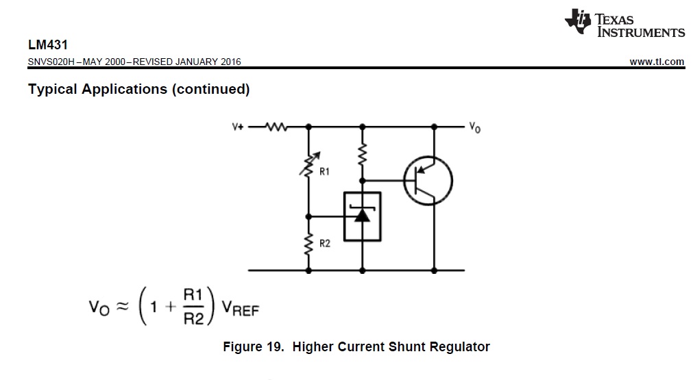
The LM431, with it's 0.4mA idle current, is on the solar panel side of the backflow protection diode.
And the reference voltage divider that measures/sets max battery voltage is on the battery side, so battery drain after dark is only about 10uA.
Dark day efficiency can be improved by using an SMD type 431 voltage reference (NCP431).
They usually have a much lower idle current (~40uA) than the LM431 (400uA). And the reference current is also lower than the LM431 (2uA), so the voltage divider can be made with higher value resistor. Downside is that you then must add a PNP transistor to absorb solar panel current.
Leo..
Edit: Can also use a 5volt, 5.5volt or 6volt panel with this circuit (no change).
That might also add a bit on dark days or at dusk/dawn, at the cost of a slightly larger panel.
NO, if both were the same dimensions, they both receive the same amount of solar energy,.
Say 10W.
12V panel will supply 10W at 12V ... 10 / 12 = 0.83A.
5V panel will supply 10W at 5V... 10 / 5 = 2A.
A 12V solar panel on a cloudy day will deliver more current than a 5V solar panel on a cloudy day
Not if they are the same size/power rating.
A 100W 12V solar panel will supply more current on a cloudy day than a 12V 10 Watt solar panel on the same cloudy day.
In any level of solar radiation a 100W panel will deliver more POWER than a 10W panel, no matter what the output voltage rating.
(Except when the solar radiation is zero.)
'Ye Cannae Change The Laws of Physics'
Tom...
PS, Please guys state the conditions before making those sort of statements.
Well I was just trying to understand why it would be better to use a higher voltage panel and shunt regulator versus a lower voltage panel with no shunt, assuming the panels would be the same size. And I guess it comes down to whether your charger is linear or switching. If it's switching, it seems it would be pretty much the same either way, with no shunt required, since the panel power would be the same. But even with linear, while the high voltage panel would give some usable current at lower illumination, it would provide less current at full illumination even before you start shunting it. Anyway, it was just not obvious to me that the high voltage panel is necessarily the best option.
I was hoping with my 6V, 1.6A (Vopen circuit ~ 7V) I can drop down the voltage to ~5.95-6V and send it to the supercapacitor (with smartbypass diode in between)
Weird thing is with no load to the regulator and I am trying to adjust the voltage to 6v it keeps going back to 0.5 volts slowly (multimeter readout), I tried this with a DC power supply and the solar panel.
I kept the screw driver off the potentiometer to avoid any wrong readings like the site says.
Now I am turning it to see If I went too far out of range.
Site says:
In addition, the potentiometer has no physical end stops, which means that the wiper can be turned 360 degrees and into an invalid region in which the output voltage is set to approximately 0.5 V.
Note: I pressed the LED output button for about 2 seconds to turn it off and save power.
I get a slightly more accurate voltage output reading by ~0.1V from the multimeter vs display.
this is dropping my ~7 volts from the solar panel to 5.8 volts, only downside is now I won't be able to step up voltage when it's almost evening time,etc...
I see that you still assume that a solar panel is a voltage source.
The DC/DC converters probably go apeshit when voltage collapses during startup.
Try a large electrolytic buffer capacitor on the DC/DC converter input (1000uF or more).
Still don't understand why you go through all of this for a 5F supercap that most likely can't get a sleeping WiFi station through the night. Good luck. You need lots of it.
Leo..
I understand a solar panel is a current source.
Tbh, I don't know enough about circuit design or have enough schematic design experience to figure out the shunt regulator setups, I understand some of it to an extent.
Everybody is mentioning some type of diode but not mentioning their current limitations enough.
The smart bypass diode mentioned below is a good future proof solution.
Connecting to the buck/boost converter is easier to for me to understand/do, but I'm deciding to forego the use of the buck/boost converter in the beginning.
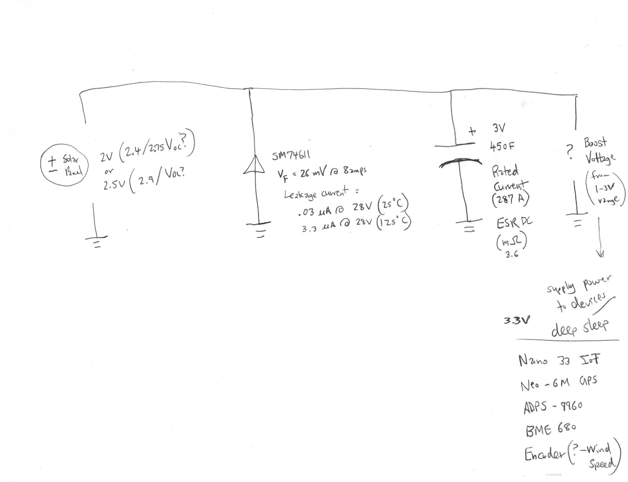
I want to keep it as simple as possible:
Solar panel (2 or 2.5V)
SM74611 Smart Bypass Diode
(prevent current leakage to solar panel in dark, .026 Volts Forward voltage drop at 8 Amps, 0.03 uA reverse current leakage at 28V)
??? (Boost voltage from 1-3V to 3.3 volts - even though lots of MCUs and peripherals are able to operate at lower voltages, most of the new Arduino/developer boards out there are still running at 3.3V )
I'm experimenting with different voltage solar panels. A lot of them will have their nominal voltage rating, and then their open circuit voltage ratings. As soon as a I apply a load/draw current though, they still operate near the open circuit voltage on a sunny day.
Some of the voltages I've experimented with:
V/Voc
12/13.1
6/7
5.5/6.2
4.5/5.1
3.5/4.1
Next I'll be trying the find 2.5V and 2V panels to see what is the max Voc I can get to supply power to the supercapacitor and not go beyond the 3V rating of the supercapacitor.
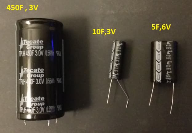
In terms of supercapacitor cost I'm finding the 2.7V/3V range to have the most amount of Farads and price/Farad value.
Here is a photo of size comparison:
Here is the best schematic I could come up with. Hopefully I didn't make any mistakes.
No, use a 4volt/150mA panel for a single 450F supercap, and a (2.7volt) shunt regulator.
Can use the LM431 diagram I posted. Replace the 120k for a 100k, and don't use the 330k.
Charge time with that setup will be several hours though.
Did you see the 72H leakage of 1mA in the datasheet?
A supercap will leak a lot more than that in the first hours of being charged.
What is your reasoning to use an expensive/problematic supercap over a cheap/easy LiFePo4 battery.
The blocking diode in your diagram must go between solar+ and supercap+
not from + to ground.
Leo..
I've been reading up on Cubesats, and for a low-orbit satellite supercapacitors have some compelling advantages. For a 90-minute orbit, the satellite is in full sun for about 60 minutes, and in "eclipse" for only 30 minutes. And there are never any cloudy days. So you would think it would be easy to provide enough current for 30 minutes in the dark. Also, supercaps have virtually unlimited charge cycles with no deterioration, which is defintely not the case with batteries. And the supercap can both charge and discharge almost without regard to temperature.
But so far all the systems I've run across that use supercaps use them only in a hybrid arrangement. In one case, the supercap was used to provide the power spikes needed for RF transmission, and the battery did everything else.
I think the bottom line is that supercaps just don't store enough energy in a small enough package to work as the sole storage format for satellites. I think Andreas comes to the same conclusion for most hobby projects.
Nice video.
I think he did miss some important points when charging supercaps with solar.
Low charging efficiency (as well as low discharging efficiency).
A 4volt panel directly connected to a supercap with a SOC of one volt only uses 1/4 of the power of the panel. You should use the same buck/MPPT technology for charging the cap as you do for discharging. More complicated electronics, or an over-sized panel.
Leo..
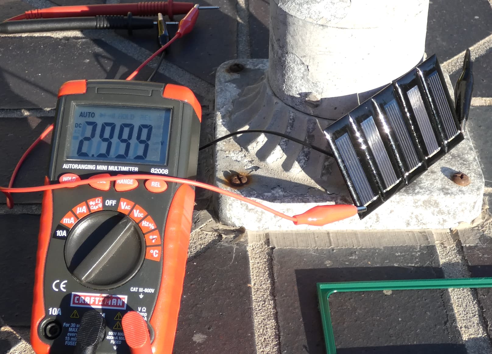
Thanks. I overlooked the fact that if I use the same voltage solar panels in series that the current will drop to the lowest current amount on a panel.
I built the 0.5V,100 mA (~0.6Voc peak) set of 5 solar panels in series (~2.999 Voc peak then drops slightly to ~2.98V), it's rated at 100 mA which is less than the current consumption of the Nano IoT and 3 peripheral devices currently (I haven't optimized power usage yet). My next goal is to get the 250 mA version of these solar panels.
The CAD model can be downloaded here in case any one wants to 3d print the case or modify it:
With this solution I wouldn't have to use a shunt regulator and resistors (although I'm not ruling them out, the current limitation is what I'm concerned about if I ever expand the initial setup I have with more sensors,etc..).
The smart bypass diode takes cares of the reverse current flow at night/dark days.
Regarding, the current leakage how would one estimate that in the first few hours?
Is there some type of formula?
In solar cells there are 2 diodes to be used. One is a bypass diode and the other is a blocking diode.
In the case of a bypass diode when multiple cells are used and one cell gets blocked, the bypass diode will take the solar panel out of the circuit instead of allowing the entire supply to collapse.
It seems OP lives in Irvine, California (educated guess).
With 217 average sunhours (7+ a day) in in the lowest month of November.
So he might be able to get away with a small-ish panel and a supercap.
Not all supercaps are made equal.
You seem to have a lab supply and a DMM. Why don't you see for yourself.
Leo..
Which boost converter are you planning to use with your single supercap.
Very few work down to 1volt.
That includes an LM2596 and S7V8A (2.7volt minimum).
I copied this NCP1402 board for a supercap project, with a Chinese/clone NCP1402.
Because the chip manufacturer (not Sparkfun) decided to retire it.
Leo..