I recently bought an ESP8266 development board from Amazon and decided to store it. A few days ago, I found that the USB Type-C port is broken, and I have to manually connect the usb c and wiggle it aroudn to my Mac to recognize it. The issue has worsened daily. I’ve been trying to find a workaround, but I’ve been unsuccessful for the past day and a half. I came across a solution where I could use an Arduino Uno R3 as a USB serial passthrough to upload code to my ESP8266 development board.
i have the right com port selected from my arduino and also the right board selected (Nodemcu Esp8266 12e development board or something close to this (it used to work with his before))
I am trying to upload the basic example blink code
The lights on my board are turned of becuase i havent connected it to my computer when i took the picture
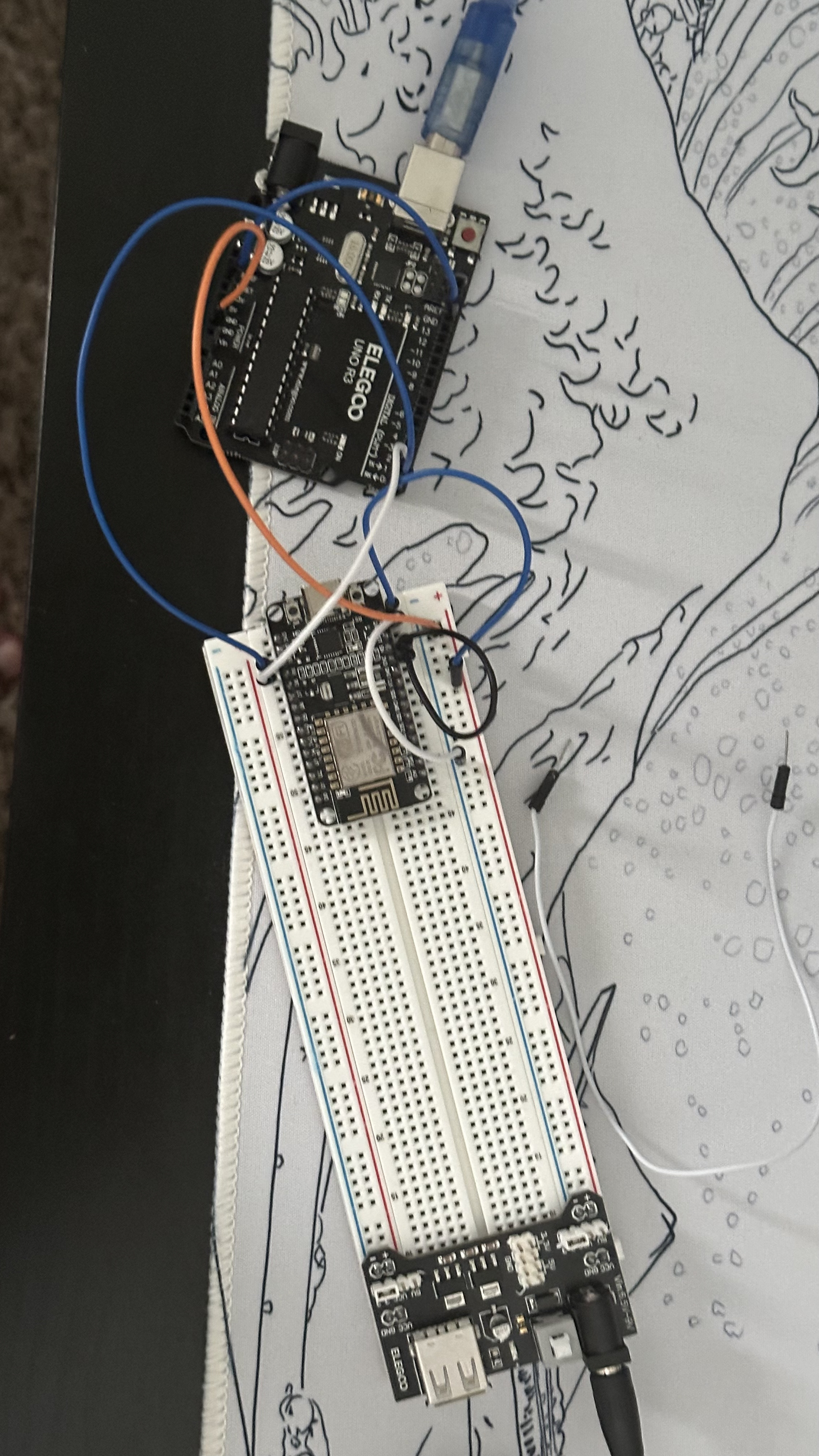
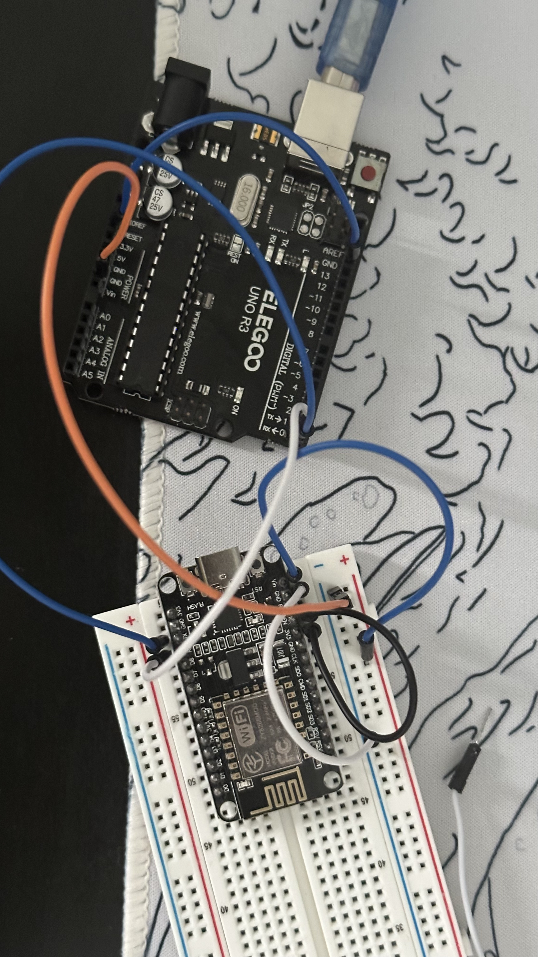
Here is the connections
Arduino rst pin to gnd of itself
the gnd of the arduino to the ground rail of the breadboard and tehn from there to through the white wire to the gnd of esp8266
tx(arduino) to rx esp8266
Rx(arduino) to tx esp8266
Vin on the esp8266 to an external bread board powersupply from whihc its + to the red rail and - to the ground rail
adn fially the EN pin of the esp8266 to the 3v3 pin of itself
i have put my MCU into boot mode/ flash mode by using both methods tell me if this is the wrong way to do it.
hold down flash button and then press the rst button and then release flash button and then press upload
holding down teh flash button while turning on the power supply
The following is everything that gets printed in my Arduino IDE output:
Variables and constants in RAM (global, static), used 28104 / 80192 bytes (35%)
║ SEGMENT BYTES DESCRIPTION
╠══ DATA 1496 initialized variables
╠══ RODATA 920 constants
╚══ BSS 25688 zeroed variables
. Instruction RAM (IRAM_ATTR, ICACHE_RAM_ATTR), used 59667 / 65536 bytes (91%)
║ SEGMENT BYTES DESCRIPTION
╠══ ICACHE 32768 reserved space for flash instruction cache
╚══ IRAM 26899 code in IRAM
. Code in flash (default, ICACHE_FLASH_ATTR), used 232148 / 1048576 bytes (22%)
║ SEGMENT BYTES DESCRIPTION
╚══ IROM 232148 code in flash
esptool.py v3.0
Serial port /dev/cu.usbmodem1101
Connecting......................................_____
A fatal esptool.py error occurred: Failed to connect to ESP8266: Timed out waiting for packet header
If you are unable to re-solder the faulty connections, you can power the ESP8266 via the VIN pin or barrel jack and perform uploads using an FTDI adapter.
From what I can tell in your photo, you appear to have the 5V pin on the UNO connected to the ground (blue) rail of the breadboard. The you have a white write from the same rail going to GND on the ESP8266.
I also don't see a ground connection between UNO and ESP8266. (Probably just as well....)
Please check your wiring carefully before attempting to power anything again!
Thx for the response I see what u mean but that only becuase of the angle I took the photo from
Arduino rst pin to gnd of itself
the gnd of the arduino to the ground rail of the breadboard and tehn from there to through the white wire to the gnd of esp8266
tx(arduino) to rx esp8266
Rx(arduino) to tx esp8266
Vin on the esp8266 to an external bread board powersupply from whihc its + to the red rail and - to the ground rail
adn fially the EN pin of the esp8266 to the 3v3 pin of itself
Just realised, Rx/Tx are marked from the MCU perspective, e.g. Rx is to receive data (from UART) into the MCU, and vice versa for Tx. Since you are defeating the MCU on the UNO by connecting to RESET to GND it sounds like this is using the onboard UART to program the ESP rather than using the UNO itself as an ISP programmer. In that case, the connections would need to be:
Rx to Rx (UART Tx to MCU Rx)
Tx to Tx (UART Rx to MCU Tx)
You are, as it were, replacing the UNO's 328P with the ESP8266.
OK so i have connected the TX-TX and RX-RX of the both microcontrollers
i still gives me this error
. Variables and constants in RAM (global, static), used 28104 / 80192 bytes (35%)
║ SEGMENT BYTES DESCRIPTION
╠══ DATA 1496 initialized variables
╠══ RODATA 920 constants
╚══ BSS 25688 zeroed variables
. Instruction RAM (IRAM_ATTR, ICACHE_RAM_ATTR), used 59667 / 65536 bytes (91%)
║ SEGMENT BYTES DESCRIPTION
╠══ ICACHE 32768 reserved space for flash instruction cache
╚══ IRAM 26899 code in IRAM
. Code in flash (default, ICACHE_FLASH_ATTR), used 232148 / 1048576 bytes (22%)
║ SEGMENT BYTES DESCRIPTION
╚══ IROM 232148 code in flash
esptool.py v3.0
Serial port /dev/cu.usbmodem1101
Connecting......................................_____
A fatal esptool.py error occurred: Failed to connect to ESP8266: Timed out waiting for packet header
i have put my MCU into boot mode/ flash mode by using both methods
hold down flash button and then press the rst button and then release flash button and then press upload
holding down teh flash button while turning on the power supply
These work but the timing is fiddly and can take a number of attempts to get it right, but it usually works - eventually.
Obviously if you can get the USB connector soldering re-flowed and the connector fixed then that would be ideal. Failing that, the FTDI adapter suggested earlier is handy as you can connect not only the power and Tx/Tx signals, but also the DTR pin via a small capacitor (4.7uF or 10uF would be fine) to RST on the ESP, which would take care of the reset signal. They are quite cheap to buy.
One other option you can get by with for the time being, is to remove the 328P chip from its socket - handling it carefully so as not to damage its pins and noting its orientation - and then dis-connecting the RESET pin on the UNO board from GND and again, via a small capacitor*, connecting it to the RST pin on the ESP. The chip can be replaced afterwards. Of course, if you are going to want to do this frequently, then removing the chip every time is going to be inconvenient and the chip will get damaged eventually. The FTDI board is the better option as it does the same job with no messing around or risking damage to the chip and leaves you with the UNO board available for some other project.
Actually, I am not sure one would be needed in this case as there should already be one on the board, but might be safer anyway.
You are using an UNO with a 16u2 as a USB to TTL converter it seems, so it should do the trick.
I tend to just upload 'Blink' to the UNO first and then leave the RST pin of the UNO unconnected.
Vcc of the nodeMCU should be connected to 3.3v on the UNO (using the UNO's 3.3v regulator) Or Vin of the nodeMCU should be connected to 5v of the UNO.
They should share GND.
Keep in mind that for any of the other pins of the nodeMCU 5v logic levels could result in damage to the pin (The rx pin usually has a diode and a 3.3v pullup connected to it and is 5v tolerant as a result, but none of the other pins are !!)
Simplest solution to put it in flash mode is to connect GPIO 0 (D3) to GND and press reset on the nodeMCU.
A schematic would make things a lot clearer, either hand drawn or with a simple drawing program or with a circuit maker web based thingy.
Also please make sure there is nothing connected to GPIO 2 (D4) that could ground it.
Edit : i would not use an external adapter to power the nodeMCU, things may only get confused from that.
Start with securing the mountings with a soldering iron and a tiny bit of solder on the tip so it won't move any more. Only the USB 2.0 pins (the 2 pins at the center of the plug) and GND & vBus are actually used and connected. A tiny soldering heatgun will probably do the trick, but even with an iron, i am sure it can be done.
I would also add that if you are going to attempt this with an iron, add plenty of liquid flux prior to soldering and have only a small amount of solder on the iron. The solder should pool and not try to bridge. If it dries out, then add more flux. A heat gun, if you have one is even better. Add plenty of flux and heat and the solder should just melt and pool at the pins.