Despite the 20 years of experience with electronics can't seem to figure out what type of circuit to use in this case. There are 6 input switches which need to be used to switch on the arduino itself and ws2812b led strip at thd same time to reduce standby current. Another option is to use relays but those would need to be placed outside of the existing enclosure due to size and would result in too many wires being used. Basically need to switch on logic level p-channel mosfet by applying +5V power source at the gate.
Use a signal n-fet on the gate, with its own gate pulled down. You can drive that with 5V to drive the p-fet. You can expand this to control multiple p-fets with one n-fet.
I am not sure what you are trying to do.
You can programmatically control the power to the WS2812 strip with the FastLED library. See the Managing power in FastLED section of the documentation.
Thanks. I think this should work despite the arduino boot time since switching on any input before connecting power works immediately.
Currently planning to use IRF7420PbF due to it's low profile.
If you keep it pulled down you are good without the Arduino. Boot time should not be an issue.
Be aware that this circuit has a charge-up time. For an instant when you connect the power supply, while the gates are not saturated, full power will pass through the p-fets, but that should not affect this, I think.
This is a circuit that the community helped me put together that has the same principle. It has steps to minimize the initial flood to a touch of voltage with an infinitesimal current.
It's for a self-latching Arduino power supply controller.
OP wants to cut all power to the LEDs when not in use, using p-fets as switches.

Here is some block diagram only to see what is required.
Using only one mosfet with multiple input switches would be the best thing to do due to limited space on perfboard. Not sure how that would interfere with the arduino inputs though.
No latching necessary in this case.
Previous post deleted.
Can't you switch LED strip ground, which an N-channel mosfet.
They usually have better power/logic specs than a P-channel fet.
Switching LED supply or LED ground won't make any difference.
You should of course switch the LED strip pin to INPUT before turning the LED strip off.
And have a ~330 ohm resistor inline.
And bypass the LED strip supply with 1000uF.
Your diagram shows 5volt to V-in, which is wrong for a 5volt-logic Arduino.
Leo..
In actual circuit 5V Arduino power pin is used, not V in.
If the ws2812b is switched together with arduino at the same time then there is no need to be concerned about parasitic currents trough ws2812b data pin.
N-channel mosfets might be better, but it seems like keeping the star ground intact is more beneficial for some reason.
Probably solid state relay with multiple inputs and one output would eliminate any possibility of interference between inputs, athough it might be too big.
Still can't find any typical wiring diagrams for transistors with multiple inputs and one output except for multigate mosfets but those usually have only two gates.
Multicannel optocoupler with one transistor output also could be an option if it's possible to find one.
The resistor is there for two reasons.
To protect the first LED in case LED supply becomes disconnected.
To absorb destructive standing waves in the Arduino<>LED wiring.
Source of the N-channel fet can still go to that star ground.
A diode OR is typically used for that.
Leo..

Doodled a quick circuit with diode OR gate wnich also isolates each input between another. Will see if it works somehow since I'm more familiar with troubleshooting instead of designing circuits for highly "specialised" applications.
By the way diodes are accidentally reversed in this drawing.
According to the link below ground must never be disconnected if it's used by multiple devices.
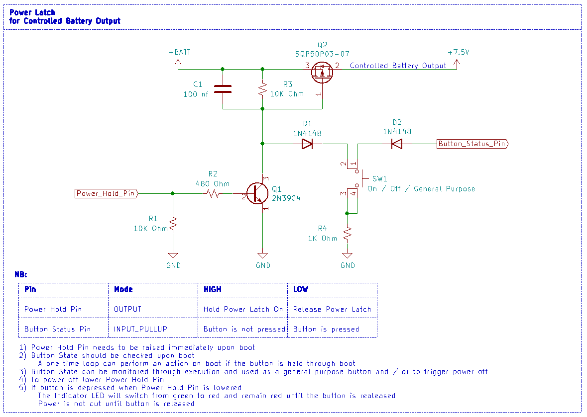
Here's the circuit I use for exactly this purpose, this is just for the microcontroller to switch power on to the LED string. If you want to switch power on to the micro controller you'll need a button like @er_name_not_found posted initially.

Seems weird that there is no need to dissconnect both rails according to the circuit above even without remowing power from controller to prevent any leakage trough data pin.
Currently trying to decide if it's worth ordering some schottky diodes to slightly reduce the mosfet Rds on resistance since bigger leakage current from schottky diodes shouldn't make any influence on arduino inputs.
You only need to disconnect the +5V rail from the LEDs, you won't get alot of leakage through the data pin doing it this way. I just tested a string of 27 WS2812B LEDs with the 5V rail off and 5V available to the data pin, there is a current flow of 300uA through the data pin (this may not be a function of the number of LEDs in the string), but testing a newer WS2812B LED there is 0nA leakage. It might be best to check this for your particular LEDs. In any case, simply writing 0 to the data port will reduce any leakage to zero while the +5V rail is disconnected as well - ie:
//LEDs off
digitalWrite(led_pwr_switch_pin, LOW);
digitalWrite(led_data_pin, LOW);

//LEDs on
digitalWrite(led_pwr_switch_pin, HIGH);
delay(t_5v_rise_time);
leds.show();
In addition to the above, if you were to use an N channel MOSFET and only disconnect the 0V rail from the LEDs, you do get alot more leakage through the data pin. On my string of 27 LEDs I am getting 32mA leakage with 0V disconnected, 5V connected and data pin at 0V.
Therefore I would say the above method (P channel +5V rail switching) is the simplest and most effective for stopping any leakage current while LEDs are intended to be off.
1 Like
If one also disconnects the negative rail on arduino then there shouldn't be any leakage through data pin?
I happen to have IPD06N03LA lying around so this should prevent analysis paralysis while choosing the right p-channel mosfet since there is always one parameter or unrelated issue which delays the decision.

As long as you also isolate the 5V rail that should work fine.
Just remembered that I have added some 1 kOhm capacitor inrush current limiting resistors in series with reed switches so that might not allow sufficient opening of the mosfet. Probably the only solution would be to remove the debouncing capacitor on particular IO and resistors from reed switches, but that would require fiddling with the reed switch holders and heat shrink tubes once again. Or another solution would be to place the 1 kOhm resistor in series with the capacitor instead of the reed switch.
As said earlier relay would be too bulky for the enclosure which would require external placement and a rats nest of wiring going everywhere which is not a good on a bicycle.