The power supply is 4 AA batteries, so 6V. So, concluding from your reaction and MarkT's (who mentioned 4.5V(?)), that isn't good for the Velleman module..? I would think that 6V is fairly close to the 7V that is indicated in MarkT's diagram, resulting in a less effective but nonetheless working transmission - or am I utterly wrong in thinking that? I'd love to hear your thoughts. Cheers.
"Close" isn't good enough, especially when it's too low. That flat spot is the bare minimum level you need to reach, and in normal use you will want a healthy margin above that. If you check the datasheet for the MOSFET, you will find that most of the test conditions is the Typical Characteristics table specify a VGS of 10V. That means the manufacturer designed this transistor to be used with at least that much voltage applied to the gate. This is not a logic level MOSFET, stop trying to use it as one. Get something that's right for the job.
Without enough gate voltage to create the conducting channel, the VDS voltage will be much too high, causing excessive power dissipation in the MOSFET that could damage it if it is not cooled properly. Even if it is not damaged, it will take power away from the load and severely reduce efficiency.
About your diagram, I found it hard to figure it out, because you've drawn it differently from how I've learned it. The way I'm used to making and reading circuit diagrams is when they are drawn in such a matter that it's a closed circuit, i.e. it starts with a wire from the '+'-side of the power supply, and ends with a wire to the '-'-side of the power supply, and the whole cycle starts over. Would you be so kind as to write that diagram in this way?
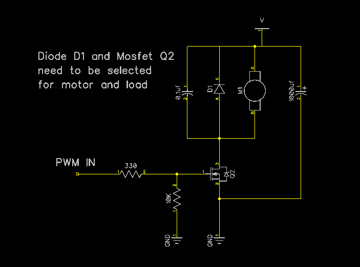
Alka's circuit contains a standard convention for drawing power connection in schematics. Because power connections need to go everywhere, it would clutter up the drawing if you drew the wires out. So a shorthand is employed.
The V with a horizontal bar under it represents a connection to the positive power supply (in this case the + terminal of the battery pack). If there were any addition symbols drawn the same way, those would also represent a connection to the same terminal of the battery pack. All of those symbols representing the same power source are electrically connected together, even though an explicit connection is not drawn on the schematic.
It is the same for the two GND symbols on the bottom. They represent the same node, and are both connected together to the 0V circuit common, in your case the battery pack's - terminal.
I recommend becoming familiar with this convention, as it will better help you draw subcircuits without having to snake unnecessary power wires all over the place.
The capacitors in alka's circuit are relatively optional, but the diode is critically important. Without it, the motor could break the transistor when it gets switched off. Do not forget it.
I understand if it's frustrating to deal with such a 'noob' like me, but I'm just very interested in learning about and understanding all of this.
Don't worry, you're not the worst I've had to deal with.