I have purchased all the parts I needed to make this too, and I feel I am soo close to getting a working unit. But with the writer of this instructable not answering me and my limited knowledge, I may have to give up on it, unless anyone can re wire it to work!
I have both a 9v (that came with my Arduino kit) and a 12v supply, both power the Arduino and the screen ok.
I’ll keep tinkering but I doubt I’ll get anywhere!!!
Intelekt:
Does anyone know of any similar projects that work that i can try?
There's an example on how to read a button in the IDE - the Button example uses an external pull-down resistor (like your circuit); the DigitalInputPullup example uses the internal pull-up.
Same for reading a pot - the ReadAnalogValue example.
I'm sure there are examples for your specific display on how to display stuff and how to connect it.
Get those working; then combine all into one code that does what you want it to do.
BUT I’ve now got a working screen, all I did was reverse the placement of the resistors and input wires, looking at the first fritzing image with the buttons and pots it seems to show the resistors and input wires going to the positive 5v side, I’ve just swapped them to the negative gnd side and it works...!!!
The joy of using instructables without knowing what you're doing...
That code you posted before is of the same quality as the circuits... lots of delay() calls, making for highly unresponsive code.
wvmarle:
The joy of using instructables without knowing what you're doing...
That code you posted before is of the same quality as the circuits... lots of delay() calls, making for highly unresponsive code.
I’m doing this project because I’ve got an SLA resin printer and I need to cure the prints after printing. Plus seeing as I had some Arduino kits that I had been meaning to get into, it seemed a good time to get into Arduino finally and combine the two, but as usual I probably jumped in at the deep end.
Thanks for all of the help you’ve all given me so far
I printed it and have studied it, and things are starting to make sense now, I feel I have a loose grasp of this schematic which is of the instructable I am trying to build
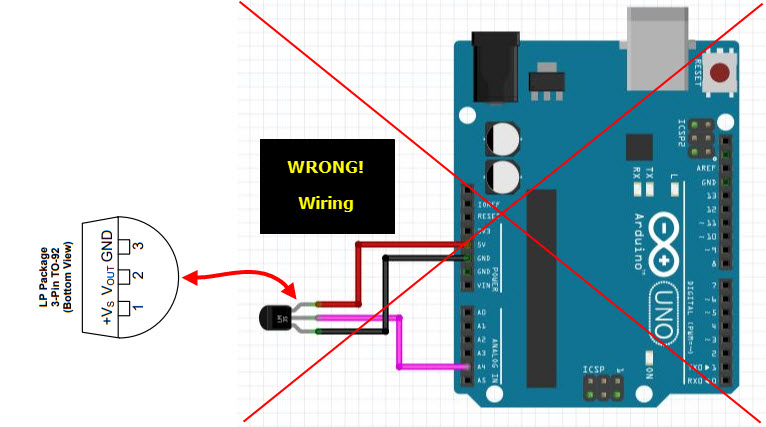
However I wired the LM35 to the way your picture suggested and it got red hot to the touch, so I put it back the way the original says to wire it and it works fine.
Your schematic appears to show the pull-up resistors between the switch and the +5v, however I have these resistors and the D7 & D8 leads on the opposite side of the switches S2 & S3 in your drawing on GND and they work as intended now.
“However I wired the LM35 to the way your picture suggested and it got red hot to the touch, so I put it back the way the original says to wire it and it works fine.”
What is written on your temperature sensor?
Do you have a link to where you bought the temperature sensor?
If you are using the LM35 sensor, the pinout is as I said and as seen in the image below.
The resistors are supposed to be pull-ups i.e. +5v——[1k]——pin ——[N.O. switch]——GND
Are your switches normally open or closed?
Do you have a link to where you bought these switches?
... but as usual I probably jumped in at the deep end.
Yes, yes you did. But you aren't really at the deep end, more of the "I can breather if I stand on my toes" deep.
Anyone who can master 3D printing has my admiration, and as long as you keep replying here with as much information as you can, you will get there. And learn an awful lot in the meanwhile.
I am a semi-expert with Photoshop and I used Autocad when it was a 2D, DOS-based command line program. (Yes, I'm old). But I have not yet been able to master the 3D drawing programs to make my own designs.
I think you are already 75% of the way to a working program. Getting the display working is the half-way point.
As has been pointed out previously, Instructables is OK for inspiration, but the instructions are rarely of much value. Be ready to do things a bit different.
Thanks, I've just about got my nose above the water is a very good analogy
As for 3d printing well its been a steep learning curve, first with an FDM printer then an SLA and another FDM, i had to get into Raspberry Pi for the FDM printers printing with PLA and then using Octoprint or Octopi as it is.
Now the arduino has started, so it seems like my head is full
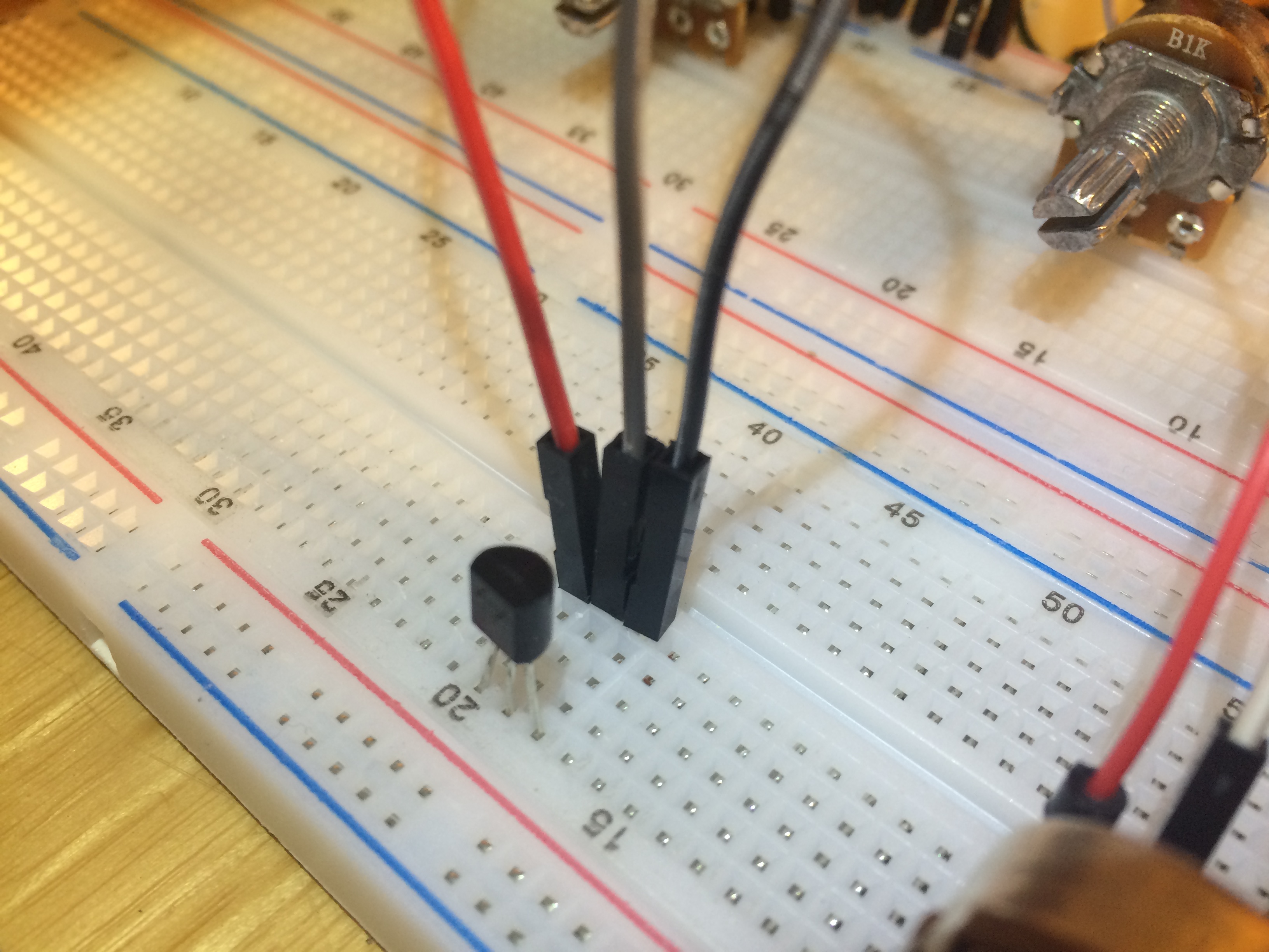
In the image below, if the red wire is +5v, the black wire is GND and the brown (middle) wire is going to A4 then you are wired as per the footprint I said for you to wire it.
The Instructable image is backward to the image below and is not correct!