Vector drawing in a led cube 9x9x9

I need some help with the code for the aurduino uno. I am doing my final project and I want to draw vectors to achieve in a cube of leds. But I have no idea how much I do the code to achieve this. The idea is, for example, drawing out a vector from the origin (0,0,0) to the coordinates of (3,4,2) (for x, y, z), turning on the LEDs which are from (0, 0,0) to (3,4,2). Also I want the LEDs to the three axes are always pinned, and if for example the vector is located on an axis, only light that not all axes.

My cube is 9x9x9 and to connect to arduino multiplexingI have used, as in this picture: http://www.donkersct.nl/wordpress/wp-content/uploads/2012/05/kubus_breadboard.png, but in my case, 9x9x9. I understand all of rows and columns, but I really need urgent help very many D: (sorry for my bad english, i`ve used Google Translate)

You want the Bresenham line algorithm for 3 dimensions:

Here's the 2D algorithm,

But it's pretty straightforward to add the Z axis, here's an example:

http://www.ict.griffith.edu.au/anthony/info/graphics/bresenham.procs

Good luck!

While Bresenham line algorithm is fine for fast rasterising it is a bit complex. For such short lines as on a 9 cube this is simpler

Why not simply use map () for each of the x, y and z axes?

Write a for loop that repeats maybe 10 times. In the loop, use map () on the loop variable to calculate each of the x, y and z values of a point on the line.

Paul

Why not simply use map () for each of the x, y and z axes?

Because a DDA wouldn't involve so many divisions?

AWOL:

Why not simply use map () for each of the x, y and z axes?

Because a DDA wouldn't involve so many divisions?

Well, its for dannyjames to decide who's time is more valuable, his or the Arduino's. In other words, which is more important, the performance of the Arduino sketch when running, or the project deadlines. Could be map () will be quite fast enough, and easier for him to understand & write the sketch.

Paul

Staking what I said. Forget about plot vectors. I wanted to say, I have a 9x9x9 LED cube, with their three axes (x, y, z) as in this image: http://www.instructables.com/files/deriv/FLG/GBRW/HFD15T0Z/FLGGBRWHFD15T0Z.LARGE.jpg.

The LED that is located where all the three lines of colors has the coordinates (0, 0, 0) and so each of the other 728 LEDs. What I want is that the LEDs of the "axis" of the cube are always turn on. And besides that, if I wanted to turn on the LED on the coordinate (6, 7, 8 ) and also the (6, 8, 8 ) and also the (8,8,8 ) and so would be forming a small line in my nature. Please, I really need your help with the code, I need to guide me whom I do. [The coordinates of "axes" in my nature would be something like:
X axis: (8, 4, 4), (7, 4, 4), (X-1, 4, 4)
Y-axis: (4, 8, 4), (4, 7, 4), (4, Y-1, 4)
Z axis: (4, 4, 8), (4, 4, 7), (4, 4, Z-1)
where the origin of the axes would be (4, 4, 4)
I say in quotes because the axles to turn the LEDs on the coordinates above, 3 axles are evoked in the center of the cube]

With the map () function could be used, but not sure.
Just imagine a small part of the code which could be as follows:
cube.set (2,0,2, ON);
cube.set (1,1,2, ON);
cube.set (0,2,2, ON);
Or you could change the parameter "ON" to "HIGH".

Please help me D:

Please, I really need your help with the code

Have you posted any code?

Dannyjames, please change your post and use code tags instead of quote tags.

Also please post a schematic of your 9x9x9 cube. The Uno does not have enough outputs to make a 9x9x9 cube in the same way as a 3x3x3 cube. How have you made more outputs? Shift registers?

Do you need help designing the 9x9x9 cube first, before worrying about drawing vectors?

Paul

dannyjames:
I am doing my final project ...

If we do the work, do we get the diploma?

fungus:

dannyjames:
I am doing my final project ...

If we do the work, do we get the diploma?

jajaja pues podría poner vuestros nicks debajo de mi nombre... que no hombre, es proyecto de final de semestre, de primer semestre de ingeniería eléctrica

PaulRB:
Dannyjames, please change your post and use code tags instead of quote tags.

Also please post a schematic of your 9x9x9 cube. The Uno does not have enough outputs to make a 9x9x9 cube in the same way as a 3x3x3 cube. How have you made more outputs? Shift registers?

Do you need help designing the 9x9x9 cube first, before worrying about drawing vectors?

Paul

Hi Paul, this is the schematic http://www.pyroelectro.com/projects/8x8x8_led_cube/img/8x8x8_schematic.png

I had to resize the 8x8x8 cube. Yes, I used shift registers (ICs) to multiplex the connections and connect to arduino. The code above is the only one I found for a cube of these dimensions, but does not help me because it is only for "effects". All I want is the code I serve to illuminate the LEDs "x, y, z" coordinate constantly

I found this and modified it, but do not know what else to do:

Well you can post proper code for a start. Just select all from the IDE and copy, do not use options like copy for forum.
Then past it in between the code tags.
Then other people can compile it. As it stands all those color tags screw it up for anyone else.
I assume they mean colour anyway.

That schematic is a different way of doing things, using parallel writes to data registers.
Uses a lot more IO, but what the heck, what else you gonna do with them when running a cube?
74AC574 would be better, its a more capable current source.

You say you are using shift registers now - do you have that schematic?

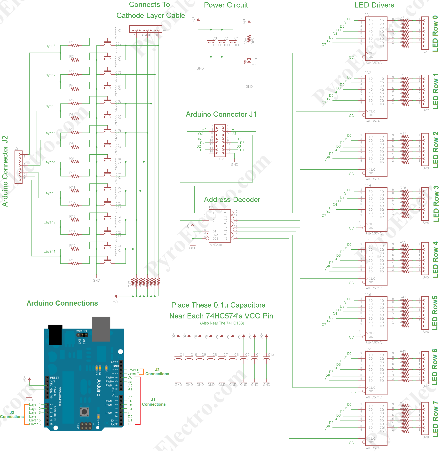
The schematic is in attachments.
The dimensions of cube are now of 8x8x8.
On the internet I found a 8x8x8 RGB code, the problem is, it is for a RGB cube, but I have modified to remove the part of "RGB".
The goal that I want to get is this:

//There are 512 LEDs in the cube, so when we write to level 2, column 5, row 4, that needs to be translated into a number from 0 to 511

//This looks confusing, I know...
int whichbyte = int(((level64)+(row8)+column)/8);

// The first level LEDs are first in the sequence, then 2nd level, then third, and so on
//the (level*64) is what indexes the level's starting place, so level 0 are LEDs 0-63, level 1 are LEDs 64-127, and so on

//The column counts left to right 0-7 and the row is back to front 0-7
//This means that if you had level 0, row 0, the bottom back row would count from 0-7,

//so if you looked down on the cube, and only looked at the bottom level
// 00 01 02 03 04 05 06 07
// 08 09 10 11 12 13 14 15
// 16 17 18 19 20 21 22 23
// 24 25 26 27 28 29 30 31
// 32 33 34 35 36 37 38 39
// 40 41 42 43 44 45 46 47
// 48 49 50 51 52 53 54 55
// 56 57 58 59 60 61 62 63

//Then, if you incremented the level, the top right of the grid above would start at 64
//The reason for doing this, is so you don't have to memorize a number for each LED, allowing you to use level, row, column

//Now, what about the divide by 8 in there?
//...well, we have 8 bits per byte, and we have 64 bytes in memory for all 512 bits needed for each LED, so
//we divide the number we just found by 8, and take the integ7er of it, so we know which byte, that bit is located
//confused? that's ok, let's take an example, if we wanted to write to the LED to the last LED in the cube, we would write a 7, 7, 7
// giving (764)+(78)=7 = 511, which is right, but now let's divide it by 8, 511/8 = 63.875, and take the int of it so, we get 63,
//this is the last byte in the array, which is right since this is the last LED

// This next variable is the same thing as before, but here we don't divide by 8, so we get the LED number 0-511
int wholebyte=(level64)+(row8)+column;
//This will all make sense in a sec

//Are you now more confused? You shouldn't be! It's starting to make sense now. Notice how each line is a bitWrite, which is,
//bitWrite(the byte you want to write to, the bit of the byte to write, and the 0 or 1 you want to write)
//This means that the 'whichbyte' is the byte from 0-63 in which the bit corresponding to the LED from 0-511
//Is making sense now why we did that? taking a value from 0-511 and converting it to a value from 0-63, since each LED represents a bit in
//an array of 64 bytes.
//Then next line is which bit 'wholebyte-(8whichbyte)'
//This is simply taking the LED's value of 0-511 and subracting it from the BYTE its bit was located in times 8
//Think about it, byte 63 will contain LEDs from 504 to 511, so if you took 505-(8
63), you get a 1, meaning that,
//LED number 505 is is located in bit 1 of byte 63 in the array

//is that it? No, you still have to do the bitRead of the brightness 0-15 you are trying to write,
//if you wrote a 15 to RED, all 4 arrays for that LED would have a 1 for that bit, meaning it will be on 100%
//This is why the four arrays read 0-4 of the value entered in for RED, GREEN, and BLUE
//hopefully this all makes some sense?

Original code that I found in internet

<originalcode.txt>

And the code modified by me:

To multiplex the connections, I used 8 and one 74HC574 IC 74HC138. Integrated circuits aka Shift registers in This Project.

ORIGINALCODERGB 8X8X8.txt (51.9 KB)

MODIFIEDBYME8x8x8TESERACTO.txt (10.7 KB)