I am now trying to use the ADS1115 at low currents (≈10μA) for my personal interest.
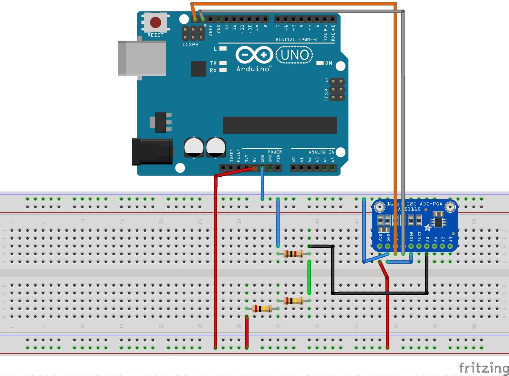
The mechanism is very simple: a 5V power supply (supplied by the Arduino) is passed through 400kΩ. This resistor is the highest in the circuit, so the current will be about 12μA according to Ohm's law.
This small current is passed through 1kΩ. Measure the voltage across 1kΩ with the single-ended A0 of the ADS1115.
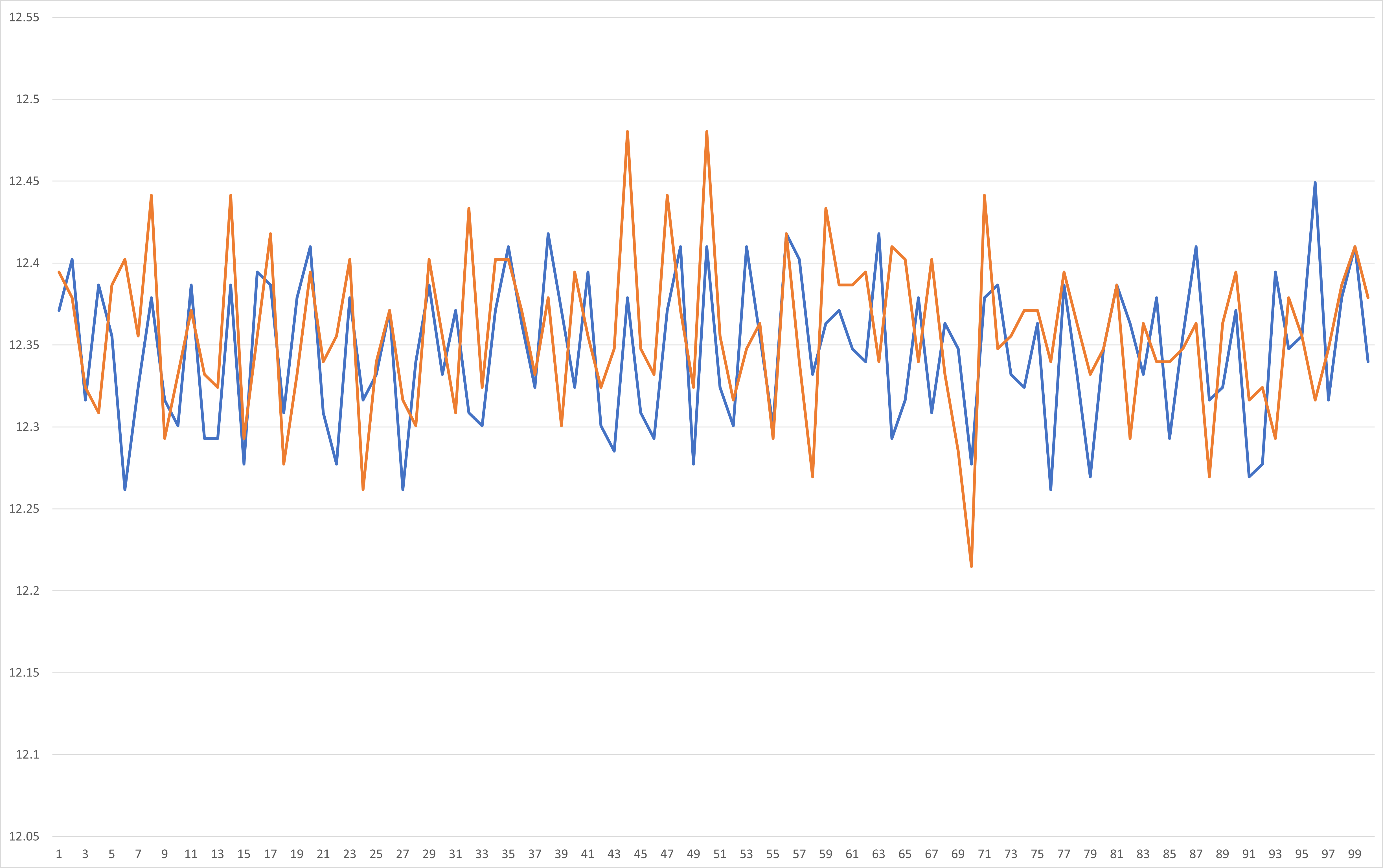
The results are attached. The measured voltage has noise or ripple-like waveform, which irritates me.
The horizontal axis of the graph is the number of measurement attempts (100 measurements in the loop) and the vertical axis is the calculated voltage in mV. The blue line in the graph is the result of measurement at 2/3x gain, and the orange line is the result of measurement at 16x gain.
This noise is very small, but I would like to solve it.
If you have any good advice, I would appreciate it.
@Idahowalker
I really liked your solution. I was also thinking of using RC filters, but I will consider other models.
By the way, as an analog solution, I had installed a bypass capacitor right after 400kΩ to reduce the noise. However, there were some problems with this method.
One of the problems is that if you change the resistor you are measuring (1kΩ in the first image I posted) to a larger resistor (say 10kΩ), the noise becomes larger again. My understanding is not good enough, but I believe that the noise is caused either by the impedance value or the small current value.
With this in mind, is there any way to reduce the noise using analog methods?
@ruilviana Here are the results obtained, with ADS1115 set to 16x gain, 560pF film capacitors. Blue is with the filter, orange is without the filter. Just by looking, there does not seem to be much difference...
We need more information, because many parts of the circuit could introduce noise.
Exactly which Arduino are you using?
What else is the ADS connected to?
The serial output seems to be going to a PC or similar. Presumably along the same USB wire as the "5V" supply; and every reading has a serial print at 9600 bd?
The divider gives a voltage of 5000 times 1 / 401 mV = 12.5mV
so why is your display showing 22?
What do you get if you connect A0 to ground?
Can you provide a schematic (or block diagram) of the whole setup; and a photo?
@johnerrington
I'm using an Arduino UNO.
The circuit is built on a breadboard, but the ADS is only connected to the Arduino.
The power supply to the Arduino and the serial output are both via USB.
Incidentally, when the power is supplied from Vin to the Arduino with a 9V battery, the noise is also present.
The serial print setting is set to 9600 bd both in the code and on the PC serial monitor.
You are talking about the first image I posted, right? This is my mistake, I used 2kΩ instead of 1kΩ for the voltage divider resistor, and the second result I posted uses 1kΩ.
I am attaching the results of my trial. Your point is very interesting and the result is noisy.
@Idahowalker
Indeed, digital filters, such as the one you introduced earlier, are a powerful option. Eventually, I may focus on choosing a better model.
Apart from that, I would be happy to discuss why noise is generated and how to handle it analogically, out of personal interest to better understand the behavior of Arduino and ADS1115.
@TomGeorge@johnerrington
Thanks for the replies, both of you!
I'll try to experiment tomorrow because of the time difference.
I'm a complete noob when it comes to "Star point". If you could give me a more detailed explanation (or share a link), that would be great.
When dealing with a mix of analog and digital circuits, noise is introduced from digital to analog through the ground, right?
If the noise gets on, the analog signal becomes a wrong signal and not a correct signal.
I would appreciate it if you could tell me how and why the grounding is appropriate when using an Arduino.
In fact, I once did a test by connecting decoupling caps (10μF) just after R1 (i.e., just behind 400kΩ). This reduced the noise at A0.
This is of course an Adafruit or Sparkfun board you have.
Not one from ebay or Amazon, with most likely a rejected or fake chip.
The ADS1115 is an absolute (voltage A/D.
I see you want to measure low currents.
Shouldn't you look at something like the uCurrent Gold from EEVblog.
Leo..
Hi,
As this not for a project, but personal interest and experimentation.
Even DMMs call it quits at mA, unless a DMM that usually is quite expensive.
As you have found you are battling noise.
If you look at EEVblog, you will see that he uses an instrumentation amplifier before you decide on ADC.
Instrumentation amps are designed for low noise, low drift, low signal applications.
I would encourage you to do some research on diff amps.
Here is an example;
This is an interesting YouTube, from the "Guy with the Swiss Accent"
Also the HX117 module is basically a diff amp setup for Wheatstone bridge applications.
Tom...
PS. Keep experimenting, great way to learn
PPS. Have you looked at using the ADS1115 in differential mode to lower your common mode noise?
@Wawa I bought the one made by Adafruit. #26 and after, the results of using it. The noise problem arises in the same way.
@SteveThackery@TomGeorge
You are right. The use of commercial products and amplifiers is very interesting (Tom, thanks for sharing the video! I'll check it out!) ), but what I'm interested in is,
so I'd appreciate it if you could stick with my trial and error a bit longer.
In addition to the results with the ”correct way” to connect the GND, I will also post the verification in the differential mode later. I'd appreciate it if you could take a look.
@TomGeorge@johnerrington
The measurement results are attached.
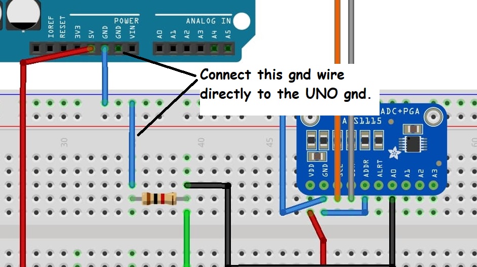
First is the wiring considering Analog GND and Digital GND.
The blue color is the "star connection" and the orange color is the same wiring as before.
Unfortunately, I don't think there is a noticeable difference. Incidentally, there was no significant difference when a capacitor was placed between VDD and GND of ADS.
Next is the result using the differential mode (A0-A1), compared with the difference between A0 and A1 in the single-end mode. The blue color is the single-end mode and the orange color is the differential mode. The blue color is single-end mode and the orange color is the differential mode.