I'm trying to turn on leds using esp32 powered using an external 5v power supply.
The issue I'm facing is that I can only (well, mostly only. more on that later) turn the leds without the power supply, connecting everything from the esp (3.3v,GND,Data).
when the power supply is connected, either with powering the esp via VIN, or only connecting the GNDs and powering it via usb, the leds won't turn on. Had it stopped here I would've assumed my circuit is simply wrong. Yet and that's where things get extremely weird, if I try to inject the data through the copper pads specifically after the third led, the leds will turn on.
I'm extremely confused hope someone will help me solve this mystery.
These are my circuits (obviously replacing the Arduino and 1.5V battery with Esp32 and 5V power supply):
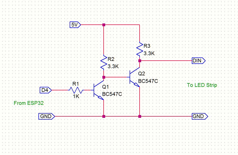
Right. You need a level shifter between the 3.3V logic and the LED strip. That link has another link to a level-shifter chip.
But you only need to level-shift one data line and it can also be done with an opto-isolator or you can make a simple transistor circuit. A "standard" one-transistor level-shifter will invert the data so you'd have to invert it in software (before it's inverted-back by the transistor). An opto-isolator can be wired so it doesn't invert.
First of all thanks!
I'll admit I've been mostly unfamiliar with most of the terms you've used, after a bit of googling I'm still not confident but I think I might understand a bit.
The amazon listing refers to it as ESP-WROOM-32 ESP-32S development board, on its back it calls itself DEVKIT V1.
Searched for the power table of the devkit, and while I'm not sure that I've landed on the correct datasheet as it seems to refer to the chip instead of the complete board, it seems like it should light up without a pull up resistor considering the table describing the WS2812B you've attached.
Voh for the ESP32 can not exceed Vdd (3.3V) without an external pull-up to a higher voltage than 3.3 (obviously) so it cant reach the minimum ViH for the LEDs (.7 * 5V = 3.5V)
but it just needs a slight raise.
He is a beginner with electonics. My circuit is bullet proof for a beginner. He will neither damage his esp32 or the LED strip or burn out his power supply.
If he decides to connect more strips in the future he can do so with out worring about back powering of devices through the Protection diodes.
When the ESP pin is configurated as output, and the pin is HIGH, then the internal top mosfet is firmly connecting OUT to VCC. I doubt a high value pull up resistor will do much there.
Maybe someone with a scope could try.
A common trick is to power the first (sacrificial) LED from a lower voltage.
Say with a 1N4004 diode from 5volt and a load resistor to ground.
Leo..