The circuit is a very simple stepper motor controller that features an arduino Nano, a A4988 stepper motor driver, 3 buttons to perform various actions, 2 LEDs for signaling the different operation modes of the motor, a fan attachment and two connectors for an external buck converter to switch from 12V (power in) to 9V (which I use to power the arduino via the "Vin" pin).
As you can see, I have included two slots where I can add two capacitors (C1 and C2), one in parallel to the "Vmot" and "GND" pins of the A4988 (which will receive 12 V in), and one in parallel to the "Vin" and "GND" pins of the Nano (which will receive 9V in).
Now... What type and value of capacitors should I use for each? And more importantly, could you please explain to me why you would choose a particular capacitor over another, so that I can figure it out for myself in the future?
Finally, if you feel like, could you tell me if you think the PCB seems okay, or if it has some obvious problems?
Thank you for your answer. I am not really sure how I should solder the ferrite bead though. And the second type you showed doesn't look like it can be soldered at all, so how should I set it up?
Also, what about the capacitors I was talking about?
Unfortunately I don't have the schematic at the moment (I started with a wrong one then basically added new elements and changed connections in the "pcb layout" tab), however I will make an updated one soon.
However, since the buttons and leds are not particularly important, a simplified version with the bare minima of connections would be the following:
Components:
12V/5A DC power supply and 9V DC power supply (provided by down converting the 12, but for this simplified circuit I think it's probably irrelevant?)
Arduino Nano
A4988 driver
Connections:
• + of 12V to Vmot pin on A4988
• - of 12 V to GND pin on A4988
(add C1 in parallel to the above)
• GND pin of A4988 connected to GND on Arduino (cause there's a copper pour, all grounds are connected)
• + of 9V to Vin pin on Arduino
• - of 9V to GND pin on Arduino
(add C2 to the above)
So... What type and capacity would be good choices for C1 and C2? A tutorial I saw online was suggesting 100uF electrolytic for C1, but didn't have C2 since the arduino was being powered via USB and not directly from Vin pin. However I also read elsewhere that electrolytic capacitors are "bad" for decoupling purposes. The informations seem to be conflicting, hence I'm confused...
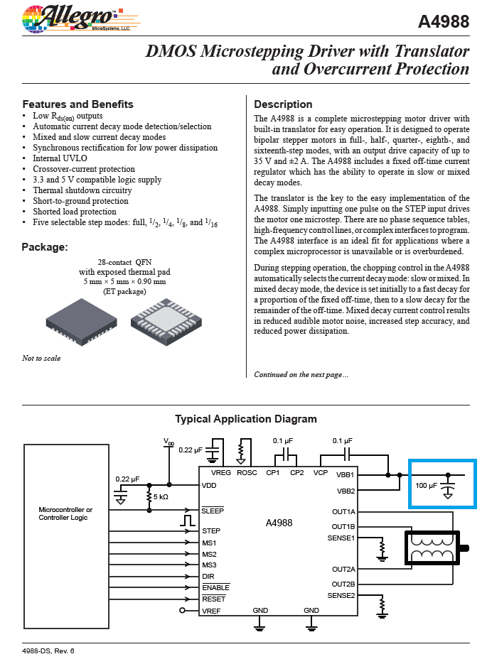
It is need to install a 100uF electrolyte capacitor in the motor power supply of A4988 for supply stability.
This is a large component and is not included in the breakout board
That is may not fit your C1 footprint.
A 100uF cap will help to smooth low frequency fluctuations in voltage when current demands change. They are like a reservoir. A decoupling cap is more in the range of 0.1uF. They help to bypass, to ground, higher frequency noise picked up from the environment and internal switching noise from digital circuits.
That is because as a general statement it is wrong, but in specific cases it is correct. Fast digital electronics requires often small amount of charge when the circuits switches. Other circuits need large amounts of charge but often do not require the charge to be available at the same speed.
Electrolytic capacitors are available for large amounts of charge (capacity) and for high voltages, but they are slow. So, you find them closer to the main power source and slower high-power circuits. They are not good for the microcontroller chip itself. There ceramic capacitors are used. Sometimes even multiple with different values.
One of the capacitors at my disposal is a 100uF/50V electrolytic with the negative and positive wires sticking out from the "bottom" circular area, so if I mount it veetically I think it should fit!
Each module you use has it own high-speed decoupling built in (it has to be, such decouplng must be close to the relevant pins of the chips (<1cm).
Bulk decoupling is also useful, especially for high current loads like motors. Perhaps ~470uF for the stepper driver carrier - has to be electrolytic for such high capacitance values, and make sure the voltage rating is large enough and polarity is right (electrolytic caps tend to explode if you get either of these wrong).
Bulk decoupling removes low frequency noise and is more useful if any sensitive analog circuitry is involved, such as audio.
I'd use wider traces for the power and motor connections to the A4988 module, these carry high currents.
That makes sense. However, how can I know if my circuit is fast or not? What determines it? In my case, I'm just controlling a stepper motor by sending impulses as a square wave to the "step" pin on the driver at a frequency of repetition of 1 pulse every about 4000 us, which should be only 250Hz.
All other pins on the circuit stay always at either high or low logic values for very long amount of times, being allowed to switch only by mechanical means (for instance, the green LED would turn on only if I press the button to start the motor).
I thought that in my case I would need capacitors at the power lines near the driver and the nano just because the 12V DC adapter I have may have some voltage spikes which could damage the driver or arduino (although Vin accepts voltages between 7 and 12 V, and I would step down the voltage to 9, so I think maybe I would've had a good of range for error even without capacitor, maybe...).
However, under this line of reasoning (just smoothing out voltage for low frequencies), electrolytic capacitors with high capacities are fine, right? However if I had on my PCB some kind of IC which works at very high frequencies (like MHz or more), in that case I would need some "faster" yet less capacious devices, and that's where the ceramic capacitors come into play. Is this reasoning correct?
If you put any capacitor on the mother board its too far from the chips on the modules to be "fast". Fast is the speed of a logic edge, measured in single-figure nanoseconds (or if you like in gigavolts per second). At these rates a few cm of pcb trace has enough inductive impedance to isolate a capacitor from the chip. Power and ground traces are kept wide to reduce this inductance.
You are saying that both the Nano and A4988 already have some small capacitors on their pins integrated in the chips themselves, to shield them from high frequency noise, right?
So, if I got this right, I need only to worry about low frequency noise, and the 470uF capacitor would be the one I would place on the "C1" footprint, right?
Do you think C2 (between Vin and GND on the Nano) had a reason to exist? I added it as I thought "another capacitor in parallel canmot hurt", but did it make sense?
The traces for the motor coils should be 0.7mm wide... Anything more I tried would make the traces be a little too close to each other than I would like (I was afraid of shorts). Would that be enough? My motor is a 1.5A NEMA 17, working at eight-step resolution and extremely slowly (only one revolution every 20 seconds or so)
High speed decoupling is to prevent malfunction, not eliminate noise - there's loads of noise on a digital supply rail normally. Without decoupling the supply voltage at the chip's pins can dip low enough to glitch the circuit into misbehaving (and the ground can rise a lot too - aka "ground bounce"). That inductance of the pcb traces is a HUGE effect at nanosecond timescales.
I'd make them 2mm wide - the pins are 2.54mm apart, the traces can easily be 2mm (80mil) if you run them straight (avoid the 45 degree angle!). If your pcb is double sided you can run traces both sides of the board to increase the current handling.
Even at a 45 degree angle the traces can be 1.5mm or so - pcb traces are only 35µm thick - so a 0.7mm trace has a cross sectional area of only 0.025mm^2, the same as 33AWG, ie tiny tiny.
The Nano and the A4988 module you are using are MODULES, not chips.
So they already have the chip-scale decoupling capacitors built into the module, and you should only need "higher level" caps on your board.
the A4988 modules typically have BIG external caps, as shown in reply #5 - I believe that those mostly handle motor current spikes rather than chip 'bypass' issues.
Whether you needs the cap for the Nano, or the other suggestions like a ferrite bead depends some on how good your external "buck module" is.
Frequency. You will need to read a little bit about electronics basics.
Any signal can be separated into frequency components (sine waves of every frequency). The math is called Fourier analysis. Ac from the power socket has a single frequency (50/60Hz). A square wave requires many sine waves with ever increasing frequency to be added.
Yes.
Yes.
Every material has a different permittivity that describes how much energy it can store when an electric field is applied. Just like many other physical properties of materials.
It mainly depends on inductance of the capacitor for fast decoupling, so long as there's enough capacitance
Too much inductance due to the size and the long thin leads and the internal wound construction
They don't, its construction - MLCC ceramics are low inductance, some film caps are wound and high inductance, some are multi-layer stacked and low inductance
If you look at datasheets of fast logic chips they quite often specify a small (0402 size) 10nF cap within mm of the pin, backed up by a larger value and size (0805 100nF a bit further back (1cm). This provides a low impedance across a wider frequency range than just one cap.
Any cap has a self-resonant frequency above which it becomes inductive. Components are very different in reality from the ideal for things like this.