What do the analogread() values mean?

Hi all,

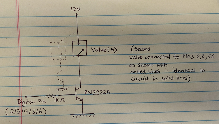
I am working on a project that requires me to read sensor values from 4 IR sensors, as well as periodically switch on 9 different valves (independent of the sensor values). The way that I have set up the code is that I am reading the input values from the IR sensors continuously, while the 9 valves switch on as follows: one switches on for 400 ms every ~5s, 4 switch on for 3s every ~15s, and 4 switch on for 400ms every ~20s.

My problem is as follows: when none of the valves are on, the "baseline" readings for the sensor values range from 30 to 50, and increases >50 when I pass any object in front of the sensor, as it is meant to. However, when the valves switch on, the baseline values suddenly drop to 10-20. Is this something I should be worried about in terms of breaking the Arduino, valves or sensors? Even if that is not the case, I am curious as to why this is happening. Could someone shed some light on this please?

The components I am using are:
1 Arduino Mega 2560
9 NResearch valves (component 161K011, details attached)
4 Sanworks IR sensors (Link)

My code is as follows:

// This code is to carry out odor training 1 in upto 4 behavioral set-ups.

#include <RBD_Timer.h> // RBD Timer is the package this code is using to set timed events. Credit: https://github.com/alextaujenis/RBD_Timer
RBD::Timer timer;
RBD::Timer dummytimer;

// Lickometers
const int lickometerPin1 = A1; float sensorValue1 = 0;
const int lickometerPin2 = A2; float sensorValue2 = 0;
const int lickometerPin3 = A3; float sensorValue3 = 0;
const int lickometerPin4 = A4; float sensorValue4 = 0;

// Valves 
const int valveOdor = 2; 
const int valveOdor2 = 6;
const int valveReward = 3;
const int valveReward2 = 5;
const int valveDummy = 4;

// TTLs for Cheetah system
const int odorTTL = 28;
const int rewardTTL = 30;
const int lick1TTL = 32;
const int lick2TTL = 36;
const int lick3TTL = 34;
const int lick4TTL = 38;
const int dummyTTL = 40;

// Event-marker variables for CoolTerm/Bonsai/Arduino SDE serial plotter
int odor = 0;
int reward = 0;

// To have variable inter-trial length, we will use random numbers from 10-21. This is an initialization.
long randomNumber1 = 10;

// Setup for time variables
unsigned long delayInterval = 6000;
unsigned long timerValue;
unsigned long dummyTimeValue;


void setup() 
{
  Serial.begin(9600); // For continuous event display/saving for CoolTerm/Bonsai/Arduino SDE serial plotter

  timer.setTimeout(3400); // Set trial length 
  timer.restart(); // Timer resets after trial length

  dummytimer.setTimeout(4000); // Set dummy valve frequency 
  dummytimer.restart();

  pinMode(valveOdor, OUTPUT); 
  pinMode(valveOdor2, OUTPUT);
  pinMode(valveReward, OUTPUT); 
  pinMode(valveReward2, OUTPUT);
  pinMode(valveDummy, OUTPUT); 
  pinMode(odorTTL, OUTPUT); 
  pinMode(rewardTTL, OUTPUT);
  pinMode(lick1TTL, OUTPUT);
  pinMode(lick2TTL, OUTPUT);
  pinMode(lick3TTL, OUTPUT);
  pinMode(lick4TTL, OUTPUT);
  pinMode(dummyTTL, OUTPUT);
  
  randomSeed(analogRead(A6)); // Seed for random number 1
  

}

void loop() 
{
  sensorValue1 = analogRead(lickometerPin1); 
  sensorValue2 = analogRead(lickometerPin2);
  sensorValue3 = analogRead(lickometerPin3); 
  sensorValue4 = analogRead(lickometerPin4);
  
  Serial.print(odor);
  Serial.print(",");
  Serial.print(reward);
  Serial.print(",");
  Serial.print(sensorValue1);
  Serial.print(",");
  Serial.print(sensorValue2);
  Serial.print(",");
  Serial.print(sensorValue3);
  Serial.print(",");
  Serial.println(sensorValue4);

  sendLickData(60, sensorValue1, lick1TTL); 
  sendLickData(60, sensorValue2, lick2TTL); 
  sendLickData(60, sensorValue3, lick3TTL); 
  sendLickData(60, sensorValue4, lick4TTL); 

  
  dummyTimeValue = dummytimer.getValue();
  if (dummyTimeValue < 400) {
    digitalWrite(valveDummy, HIGH); digitalWrite(dummyTTL, HIGH);
  }
  else if (dummyTimeValue >= 400 && dummyTimeValue <= 700) {
    digitalWrite(valveDummy, LOW); digitalWrite(dummyTTL, LOW);
  }
  else if (dummyTimeValue >= 3500 && dummyTimeValue <= 4000) {
    dummytimer.restart();
  }
  

  timerValue = timer.getValue();

  if (timerValue <= delayInterval) {
    odor = 0; digitalWrite(valveOdor, LOW); digitalWrite(valveOdor2, LOW); digitalWrite(odorTTL, LOW);
    reward = 0; digitalWrite(valveReward, LOW); digitalWrite(valveReward2, LOW); digitalWrite(rewardTTL, LOW);   
  }
  
  else if (timerValue > delayInterval && timerValue <= delayInterval + 6000) {
    odor = 1; digitalWrite(valveOdor, HIGH); digitalWrite(valveOdor2, HIGH); digitalWrite(odorTTL, HIGH);
    reward = 0; digitalWrite(valveReward, LOW); digitalWrite(valveReward2, LOW); digitalWrite(rewardTTL, LOW);   
  }

  else if (timerValue > delayInterval + 6000 && timerValue <= delayInterval + 6000 + 400) {
    odor = 1; digitalWrite(valveOdor, HIGH); digitalWrite(valveOdor2, HIGH); digitalWrite(odorTTL, HIGH);
    reward = 1; digitalWrite(valveReward, HIGH); digitalWrite(valveReward2, HIGH); digitalWrite(rewardTTL, HIGH);   
  }

  if (timer.onRestart()) {
    randomNumber1 = random(10, 21);
    delayInterval = randomNumber1 * 1000;
    timer.setTimeout(delayInterval + 6000 + 400);
    odor = 0; digitalWrite(valveOdor, LOW); digitalWrite(valveOdor2, LOW); digitalWrite(odorTTL, LOW);
    reward = 0; digitalWrite(valveReward, LOW); digitalWrite(valveReward2, LOW); digitalWrite(rewardTTL, LOW);   
  }

}


void sendLickData (int threshold, int sensorValue, const int lickTTL) 
{
  if (sensorValue > threshold) 
  {
    digitalWrite(lickTTL, HIGH);
  }
  else 
  {
    digitalWrite(lickTTL, LOW);
  }
}

Please let me know if I've missed anything, I would be happy to share further details if required.

Valve manual.pdf (98.1 KB)

Here's what I think may be happening.

Analogread() values are 0-1023 which represents the proportion of the voltage at the analog input compared to the supply voltage (nominally 5V but probably not exactly 5V). If your supply voltage is lower the value is still the proportion of the supply voltage (ie, 512 is always the middle of the range).

However, what can happen is that you sensor is sensitive to the voltage and when you are operating equipment like motors, valves, etc (genarally heavy loads, especially inductive ones), the supply voltage can't keep up and will drop. This can cause malfunctions and things like you are seeing. You should be able to verify this voltage drop with a voltmeter.

The general solution is to provide separate power supply for the heavier loads, independent of the electronics (arduino, sensors, etc) power supply.

Thank you! That makes sense.

marco_c:
The general solution is to provide separate power supply for the heavier loads, independent of the electronics (arduino, sensors, etc) power supply.

I currently have 12V battery supplies for each of the valves, and the Arduino is connected to a computer via a USB cable. Do you think the Arduino should also be connected to a wall power supply?

The basic rule for avoiding damage is that the voltage presented to a pin (analog or digital) is
never outside the range 0V to Vcc, where Vcc is the current supply voltage. This means that
you mustn't apply a voltage when the Arduino is powered-down for instance, and never
less than 0V or more than 5V when powered up (assuming a 5V Arduino).

However by adding a series resistor to drastically limit any current (such as a 10k resistor),
you can protect against damage from rogue voltages.

You can scale voltages down to the 0..5V range using a resistor divider too.

Do you think the Arduino should also be connected to a wall power supply?

That shouldn't make things worse and is worth trying.

How you resolve this depends a lot on how you have wired the circuits. You have not shared any of this info, so it is hard to give any more specific advice.

marco_c:
How you resolve this depends a lot on how you have wired the circuits.

Thank you! Here is some information on the wiring:

Two valves are connected to each of the following digital pins: 2,3,5,6 and one valve is connected to digital pin 4 (using the circuit diagram attached). I have also attached the specification sheets for the valve and transistor shown in the circuit diagram.

The connection for each of the sensors is outlined in circuit diagram 2.

Please let me know if I have missed anything.

Valve manual.pdf (98.1 KB)

PN2222-D transistor.PDF (198 KB)

MarkT:
The basic rule for avoiding damage is that the voltage presented to a pin (analog or digital) is
never outside the range 0V to Vcc, where Vcc is the current supply voltage. This means that
you mustn't apply a voltage when the Arduino is powered-down for instance, and never
less than 0V or more than 5V when powered up (assuming a 5V Arduino).

However by adding a series resistor to drastically limit any current (such as a 10k resistor),
you can protect against damage from rogue voltages.

You can scale voltages down to the 0..5V range using a resistor divider too.

Thanks! I currently have 1k resistors between the digital pins and the valve connections, and resistors set up as shown above for the sensors. Would you suggest any changes/additions to that?

arduinobaswas:
Please let me know if I have missed anything.

You need a flyback diode to be connected in parallel with valve's coil.
https://forum.arduino.cc/index.php?topic=705982.0

alesam:
You need a flyback diode to be connected in parallel with valve's coil.
Flyback diodes and why you need them - General Electronics - Arduino Forum

Thanks for the link! Do you have any suggestions as to what type of diode I should use, or some insight into how I should choose the right diode for this application? I would really appreciate it if you could recommend any resources I could look into.

arduinobaswas:
Thanks for the link! Do you have any suggestions as to what type of diode I should use, or some insight into how I should choose the right diode for this application? I would really appreciate it if you could recommend any resources I could look into.

It depend's on coil parameters (voltage, current, induction). There are lots of materials available. For example:

etc

alesam:
It depend's on coil parameters (voltage, current, induction). There are lots of materials available. For example:
Selection of Ultra-Fast Recovery Diodes Used in Flyback Circuits | Analog Devices
Fly Back Diode Selection - Page 1
How to choose a flyback diode for a relay? - Electrical Engineering Stack Exchange

Thank you so much.
I will try these suggestions, and post an update on the results on this thread.

It turns out that the valves need to be used at a holding voltage of 4V (1/3 of operating voltage 12V). To achieve this, I will be connecting the valves to the Arduino through a board (called CoolDrive) from the same company as the one the valves are from (details attached). Does this change anything in terms of what kind of diode I should look at, or how I should set up the connections (as related to the previous posts on this thread)? The connection with the transistor and resistor will remain same, but instead of connecting the 12V supply directly to the valves, I will connect it to the board, and then the board to the valves. Please let me know if you require more information.

cooldrive.pdf (372 KB)

No, I think the CoolDrive board will do it all for you (I can see diodes on there near the output screw connectors). You should be able to connect the Arduino outputs directly to the Board as they are 5V inputs.