I'm building a button box for flight sim and I'm trying to wire up several buttons into a 5x4 button matrix, alongside three KY-040 rotary encoders.
Originally I was planning to wire the encoder button function into the matrix, but then I found the encoder needs a 5V wire to function properly, so I can't connect the button to a row and a column. I am now helpless on how to wire it properly into the matrix, and I'm not sure if it's even possible.
I don't have enough free I/O to wire these buttons directly into the Arduino Leonardo.
Do you have any ideas on how to fix the problem, besides expanding the I/O?
Thank you for the reply. I'm not trying to connect the rotary encoder itself into the keyboard matrix. Rather, I just want to connect its push function into the matrix, which I think normally should be possible. I was following this tutorial: How to Build a Button Box - YouTube.
Unfortunately, I have a different kind of encoder that comes with a breakout board, and needs 5V input to function properly. This leaves me with just a single pin for the push function instead of two, which I would normally connect into the matrix.
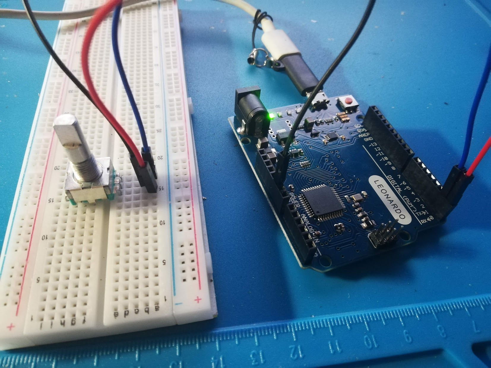
As for what's connected to the Leonardo, I have 19 buttons in total (3 2-way switches, 4 regular switches and 6 push buttons, all momentary, plus the ones on the rotary encoders), 3 rotary encoders and 4 potentiometers.
The KY-040 rotary encoder only needs Vcc for the external pullups on the KY-040 board. And the pullups are only for the encoder side, the switch is not pulled up. The push switch can still be wired as any NO push button switch so should go into a matrix like any other. You will have to separate the push switch ground from the encoder ground, though.
That is indeed a KY-040 rotary encoder. The 'CLK' is often called 'A' and the 'DT' is 'B'.
The 'SW' is connected to GND when pressed.
You have already answered your own question, it can not be combined with a keyboard matrix. [ADDED] Maybe you can, as groundFungus wrote
Have you read this comment in the Keypad library: "Re-intialize the row pins. Allows sharing these pins with other hardware".
But I don't know how and what that sharing can be.
The Leonardo has exactly 19 pins. There are 3 more digital I/O pins on the ICSP header.
The switches can be placed behind extra hardware.
There are also Teensy boards with more pins, such as the Teensy 4.1.
I have just tried desoldering the encoder from the board. Unfortunately, when I plug it into the Leonardo and try rotating it, it behaves weirdly:
Every other rotation by one detent seems to be registered just fine. However, the next rotation causes the encoder to keep switching A and B states indefinitely. The next rotation stops this behavior, another one makes it keep going, and so on...
Maybe I don't understand encoders and how to read them enough. Is this an expected behavior? Would you be so kind to provide a code snippet on how to handle this behavior? (I have tried several code snippets found on the internet, none of which worked for me).
To provide an example, I have written this code:
int encoderPinA = 0;
int encoderPinB = 1;
int prevA = -1;
int prevB = -1;

void setup() {
  pinMode (encoder0PinA, INPUT);
  pinMode (encoder0PinB, INPUT);
  Serial.begin (9600);
}

void loop() {
  int a = digitalRead(encoderPinA);
  int b = digitalRead(encoderPinB);

  if (a != prevA || b != prevB) {
    Serial.print(a);
    Serial.print(" ");
    Serial.println(b);
  }

  prevA = a;
  prevB = b;
}
When you removed the encoder from the board, you left the pullup resistors behind. Compensate by setting the pinModes for the encoder inputs to INPUT_PULLUP.
Put a 0.1uF cap from A to ground and from B to ground to help debounce the encoder switches or include software debounce in your code.
And don't use pins 0 and 1. Those pins are for the hardware serial RX and TX. You are not using serial for this code, but you will soon find out the importance of the serial port for debugging. Also if you connect some things to those pins you will not be able to upload code via the serial port. My advice is to forget that those pins exist for normal projects. Edit: comment based on mistaken assumption that the board an Uno instead of a Leonardo.
Thank you! I've tried the Encoder library, added software debounce, and it works perfectly now.
Also, thank you for the tip about RX and TX, I'm completely new to Arduino, so I'll take any advice I can get.
So I have had another look at trying to rectify this design whilst still using the KY-040 board without de-boarding the rotary encoder as per the OP's solution. Here's what I came up with and have proven it works in testing.
As a new user I was unable to add all the images and links so here's a link to the folder with them all. KY-040 Keyboard Matrix Solution
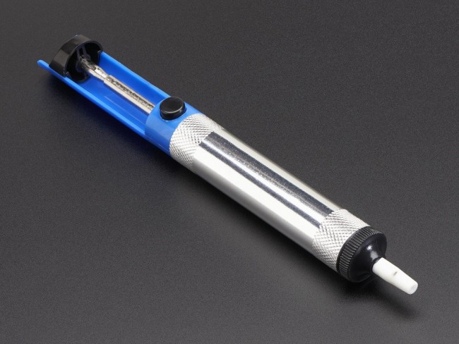
The board circuit is big enough to be able to work with, so firstly de-solder the pin as best as possible, use a solder sucker is best. Solder Sucker Link
see KY-040 Circuit Map in folder
In the circuit image you can isolate the earthed pin, do this by carefully using a scalpel or small sharp blade to cut an area around the pin, careful not to impact any other tracks. once you have cut lines down to the phenollic (the base on which the copper tracks lay) then carefully use the blade to push under the copper track towards the port pin, always working away from the other tracks, once all the copper is removed you need to solder in a new wire on the pin.
see KY-040 KY-040-Solution-9 in folder
I found the best way was to push the wire through the hole and to solder on to the leg on the top side of the board.
See KY-040-Solution-4 in folder
Using the Keyboard Matrix sketch you wont need to use the +5V, you will only need the pins in the image below. Hope this helps anyone in the same situation.

