I have finally got to the point of trying to run a program without the arduino (I am trying to wire an atmega328p chip ,with a crystal on a bread board. I am following Nick Gammon's page
showing how to wire an atmega to load the bootloader into it.
Do I need any other pins connected to make a programme work ?
I am using UNO pins 5,6,7,8,9,10 for my program and plugging into pins 11,12,13,14,15,16 on the chip which are the corresponding pins for the chip. see
I have used capacitors where needed (4) and connected pin one , via a 10k res to 5v.
I know the chip is ok because I have left the wires to the arduino in place (I remove them when checking the chip on the breadboard, they are fastened together as a plug) and I can put the chip back in the arduino and it works.
I have two xtals, one purchased with a chip from the e-bay (the chip is fine) and one purchased from Maplins. I assume they are both fine, though they both have 16,000 on the top, this is 16Mhz I presume?
Any help would be appreciated.
I have just rewired the chip onto a board with the blink sketch in it, wired an led to pin 19 of the chip, it still doesn't work so I am quite sure I am missing a connection somewhere unless the xtals are just not working (I have tried both xtals in the new layout).
Does it matter which way round the xtals go?
matelot:
Does it matter which way round the xtals go?
No, they're not polarized.
Have you done a lot of work with the breadboard before this?
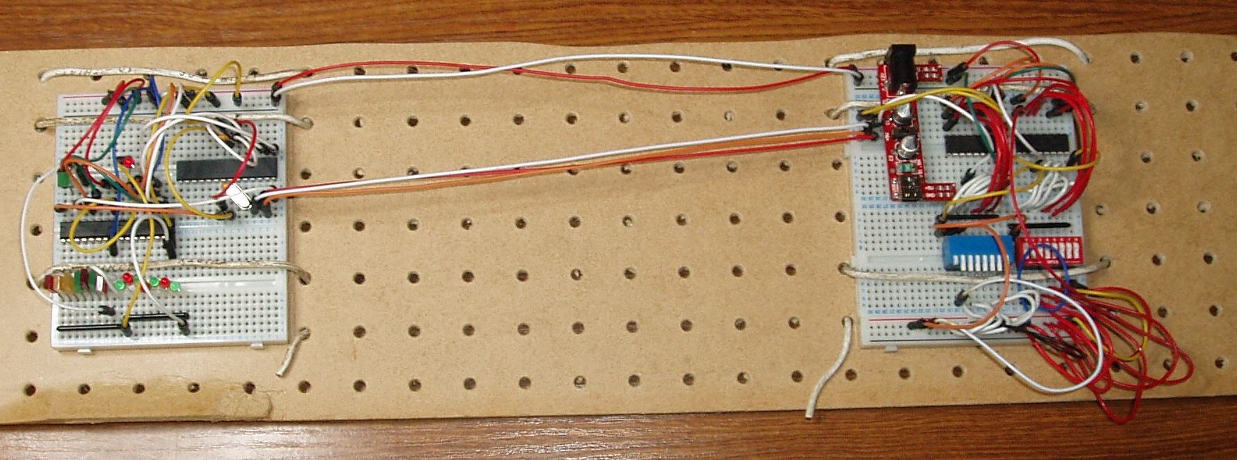
A good quality pic of your setup, where all of the wires and their paths can be seen is often helpful.
I have tidied my circuit up and taken a picture
I think I will have to save the picture to the web somewhere to allow it to be shown here, do you have any idea how I do that or where to so I can put it on here as an img ?
Click "Reply" and then "Additional Options".
Click "Browse" and select your picture.
Resize & crop it before posting so it is not more than ~1000 wide.
I have done quite a bit of work with breadboards but not wired up an atmega chip till now.
I have attached the picture it as you suggest (easy when you know how).
There are two 0.1uF caps across the two power supply leads (104's)
two 22pF caps from 0v to each side of the xtal (220's)(they are connected on the line from pin 8 (0v)for ease of connection).
So yes there are two caps from the xtal pins to ground, ie. pins nine and ten.
one 10k resistor to pin 1 as a pullup for the reset.
The positive side of the LED is connected to pin 19 (pin13 on the arduino), negative side via a 180 ohm resistor to 0v.
The LED works if I put the positive leg from pin 19 to pin 20 (5v).
The chip has just been put back in the arduino and blinks the onboard LED when powered up.
I have just tried both xtals (they are both new and from different sources so I am hoping they work).
I have done a reset by connecting 0v to pin 1.
Otherwise I am lost.
going back to my first post, I mentioned Nick's page
It does say on there that by not using an xtal at all the atmega chip has an internal xtal of 8Mhz?
Do I read that right?
I have removed the xtal and its two capacitors but the result is the same , no flashing?
Your 5V is solid (voltmeter verified) across both rails?
The rails at the bottom are labelled "5V" and "GND", but the two at the top are "(blank)" and "Gnd".
So, what's the deal there? [Please confirm.]
(I hope it's not Vsupply || > 5V).
Sometimes the crystal caps add too much capacitance - there's often enough from the breadboard sockets.
The "328" has an internal timebase option (haven't used that.)
yea, I have checked the 5v on both rails. The top one says vc between the hole and the side of the pins and the other side has + and - the same as the bottom set. Are you suggesting I could remove the 0.1uF caps?
5.07v on both rails
I have removed the two 22pF caps and the LED is blinking like a good un.
I am well past sandman time now so tomorrow I will reassemble my original circuit and try the chip on it.
Thanks so much for your very welcome help. I will have to find out more about the reason for the caps.
I have put the two 0.1uF caps back in and it still works, no 22pF caps.
You will/would need them on a proper circuit board.
The breadboard sockets have capacitance all their own.
So, the socket capacitance in parallel with the 22pF capacitors made for too much capacitance.
matelot:
I have put the two 0.1uF caps back in and it still works, no 22pF caps.
However it may seem, this is not a random "he loves me, he loves me not" approach to fitting capacitors. There is a reason for each capacitor and it is important to understand it.
The 22pF capacitors are there for "loading" or "tuning" the crystal - they make it it function as a "Colpitts" oscillator. There is a range of capacitance over which they can tune the crystal frequency, but beyond such range, there is insufficient feedback for it to oscillate. It would seem that the characteristics of your particular crystal (and perhaps, breadboard as it would seem that not all are identical and as others including Nick have had success with the nominal capacitor values) are such that too much capacitance prevents oscillation.
Another possibility is that the fuses in your chips have been set for the wrong feedback level for the crystal.
But this must not be confused with the entirely different rationale for the 0.1µF capacitors. These are bypass capacitors to prevent impulse propagation and oscillation in the chip(s) due to inductance of the connecting wires. It will never be the case that the circuit works better without them, though it may well work - most of the time - without.
I have just finished connecting the chip back into my original breadboard.
IT consists of two 4021 shift registers sending the info from sixteen switches via the atmega chip to two 595 shift registers driving sixteen LED's. I intend extending the whole thing to allow me to run an indicator board (representing the layout) of a garden railway here in Sheffield. The present board has 86 wires connected to it and only indicates about half of the present layout so a replacement would look like the national grid if I used a wire for every connection. I intend presenting my bread board to a display tomorrow to the club, during a meeting of what each member is working on (the club is the Sheffield branch of the Society of Model and Experimental Engineers).
Thanks for all your help.
I am grateful for every one.
Paul, I think when I build the circuit on an etched copper board I will leave spaces for the 22pF caps but not add them. I will of course use the 0.1uF caps as you indicate. Do you think it will be acceptable to test it and leave the 22pF out if the circuit works without them?
I don't know your name runaway pancake but thanks to all three of you for your help.
matelot:
Paul, I think when I build the circuit on an etched copper board I will leave spaces for the 22pF caps but not add them. ... Do you think it will be acceptable to test it and leave the 22pF out if the circuit works without them?
I would not advise it - and I would be surprised if it even worked without, let alone reliably and on frequency.
Note the design rules - you must locate crystal and capacitors as close as possible to the MCU pins to which it connects. If possible, the only board trace that should surround these connections should be a ground, and the 0.1µF ceramic (chip - SMD preferable) bypass capacitors should also be immediately adjacent to the MCU pins to which they connect such that the connections are as short and direct as possible.
ok thanks I will bear that in mind.
It will be a while before I get round to the final project. Its got other projects before it but I will certainly take your advice, thanks.
Try it out on your bread board first but I have found that it does work without them! However there is defiantly a reason that the engineers put them in. Reliability? Stability?