WS2811 Issue Giving Strange Colours With >1 WS2811s

Hi All,

I am having a very frustrating time with a new led strip I have designed.

Each bank of 3 LED's works great and as expected, well almost, except the middle led of the three seems to have its green and blue inverted but I'm not too worried about that. Just throwing it in there in case it is relevant!

My issue is, when I have one bank of three LEDs (one WS2811) running with the code below it works as I expect. However, when I join DO1 to DIN3 (digital out of the first WS2811 to the input of the second WS2811) and set the code to 2 leds, I get a funny hue on the first set but the second set of leds do not light up.

To be clear, when testing the two WS2811's remain connected, the only thing I am changing is the NUM_LEDS.

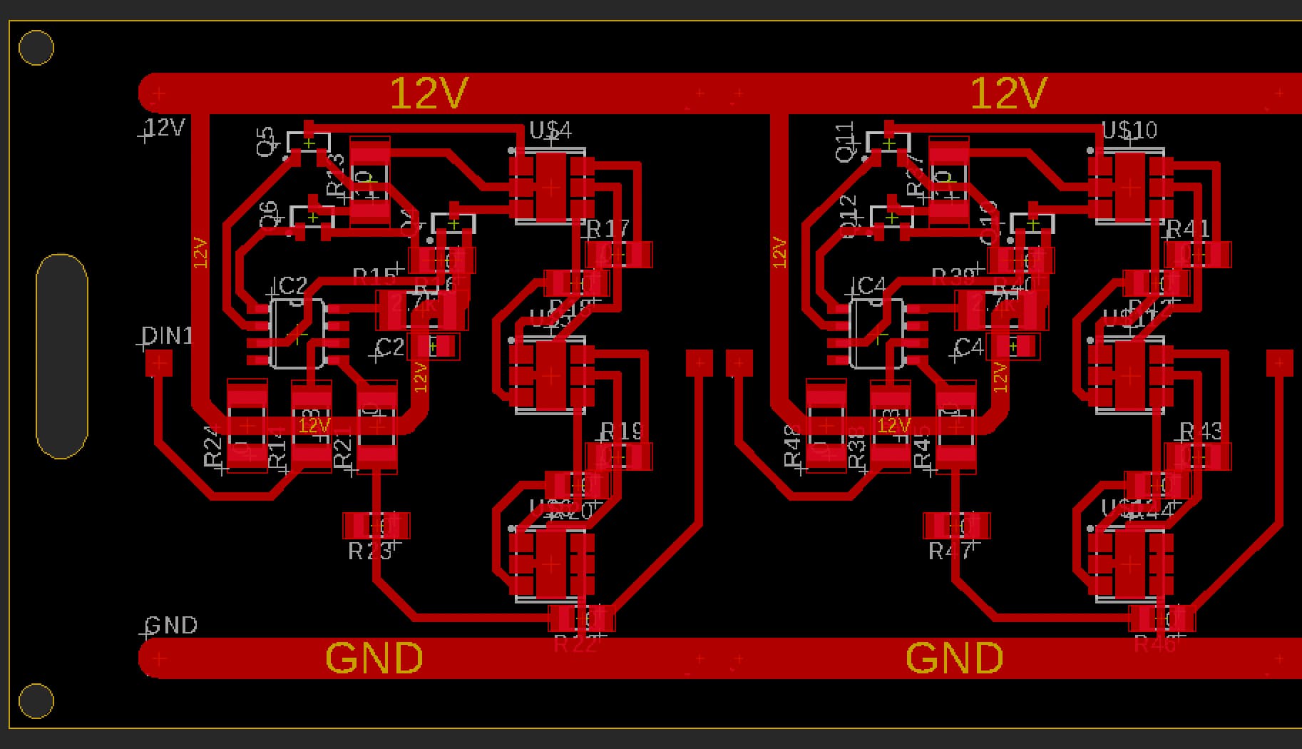
The screenshot below is for the LED strip itself, I am driving it using an arduino Atmega 2560 with the GND connected to the GND of the LED strip.

I have also tried adding a 16V 1000uF capacitor across the +12V and GND on the light strip but this has no effect.

The WS2811 chips are from JLC PCB and have what I assume to be a date stamp of 080823.

#include <FastLED.h>
#define NUM_LEDS 2
CRGB leds[NUM_LEDS];
const int Light = 6; // this is the pin I am using for the signal. 


void setup() {
  FastLED.addLeds<WS2811, Light, GRB>(leds, NUM_LEDS);
  FastLED.setBrightness(10);  // Because I want some eyeballs left
}

void loop() {
  fill_solid(leds, NUM_LEDS, CRGB(250, 250, 250));
  FastLED.show();
  delay(1000);
  FastLED.clear();
  FastLED.show();
  delay(1000); 
}

I am using a bench top power supply which seems pretty reliable. Voltage is set to 12.05 and it's drawing just over 1w overall.

I would be exceedingly glad of any help with this please.

Are you not using WS2811?

Thanks, yes I tried that as well. The code I have been testing everything with declares it as WS2811. I'll update the above code

@xfpd - Wat ar yo, dubnk? Didn't you read the original post? : )

As @xfpd correctly pointed out the original code has WS2812B declared as the led type. Correct code below for reference but still doesn't work.

#include <FastLED.h>
#define NUM_LEDS 2
CRGB leds[NUM_LEDS];
const int Light = 6; // this is the pin I am using for the signal. 


void setup() {
  FastLED.addLeds<WS2811, Light, GRB>(leds, NUM_LEDS);
  FastLED.setBrightness(10);  // Because I want some eyeballs left
}

void loop() {
  fill_solid(leds, NUM_LEDS, CRGB(250, 250, 250));
  FastLED.show();
  delay(1000);
  FastLED.clear();
  FastLED.show();
  delay(1000); 
}

@newone96

Using NUM_LEDS in "fill_solid" makes NUM_LEDS out-of-bounds as an LED. You declare NUM_LEDS as 2 (two pixels)... but in the function fill_solid, a "2" means the third element... 0, 1, 2... which you do not have.

This might be hard to see.

blink

Thanks @xfpd that's interesting, so how should I be setting this up in the code?

At the low level brightness the LEDs are still quite bright as they are large.

Your code used NUM_LEDS ... that tells you and your code the total number of LEDs to put in an array (0, 1). Inside the function, use a valid element from the array (0 or 1). If you have 3 LEDs, then set NUM_LEDS to 3 and then you can access arrayy elements 0, 1, 2 for the three LEDs.

Brightness... keep it at 10 (your preferred level)... I used 255 for the simulation.

Yes so I had the NUM_LEDs set to 2 but it wasn't working

But you told the "leds" object to take the third element (2 = NUM_LEDS) out of a two-element array (0, 1)... and since element #3 is "does not exist... nothing" it complied by giving "nothing" as a result.

fill_solid(leds, NUM_LEDS, CRGB(250, 250, 250));

@newone96

I was wrong about the use of NUM_LEDS inside FastLED... which counts 1, 2, 3 rather than 0, 1, 2.

Your code works... I just added a brightness and delay #define
blink

Are you using transistors ? what for. Why not use the normal schematic from the datasheet.

C2 is connected incorrectly, it should be between GND & VDD , not between GND & the 2.7K resistor.
Depending on what that part which looks like a transistor, really is, there should be resistor between the base and the open-collector channel on the WS2811. If it's a P-channel mosfet, maybe it's ok. Still you should just let 12v go through 3 leds to the open collector and add a resistor on the red channel. I am never sure what is on my strip, the calculation from the datasheet ends up being 3 / 18.5 = 0.162 K so something like 160R

The timing is almost the same WS2812b has a longer frame reset time, but older WS2811's may have as well (In fact there are 2 datasheets for the same chip)

Anyway, your issue is probably not in the code, but in the hardware.

Thanks @Deva_Rishi the reason for using transistors is because each WS2811 is driving a tricolour 1W led. The WS2811 are limited to 18mA which isn't enough to get the LEDs glowing brightly enough for my liking. The transistors are S8550's as per this link:

A do think it is very much hardware related even though I haven't got a clue what it is. I have also checked the fuses and the Low byte is set to 0xFF which I believe translates to the external 16MHz oscillator. I have scoped that and it is working fine.

In case you are wondering why there are so many 0ohm resistors it is because this is the board layout. It's a single sided aluminium one:

Based on needing to draw more current than shown in the WS2811 datasheet, how would be best to do this?

@Deva_Rishi You sussed it! I cant thank you enough. That cheeky little C2 capacitor in the wrong place was causing all the issues. I've left that in place (for ease) and added another 104 where it should be and it is working a treat.

In case anyone else sinks to the same level of incompetence as me....

You're a legend! :partying_face:

1 Like

Ah Ok, well i went for powering the WS2811 with 5v, and the powered an inverter-IC and used N-channel mosfets to get myself 75W of output er channel, But with PNP transistors you have to go for a 12v system. but you should put a current limiting resistor between the transistors and the WS2811 i think.

Glad to have been of service

This topic was automatically closed 180 days after the last reply. New replies are no longer allowed.