XBOX 360 Controller Hack (add macro ability)

Goal: control XBOX 360 with a computer/PIC/etc.

Problem: console USB/wireless interface is proprietary (and probably way beyond my skill level even if it wasn't).

Solution: use Arduino and hack a retail controller.

At this point, it is still just in the tinkering stage. I have an Arduino Mega, a wired controller and a couple bins full of electronics 'stuff'.

Several decades ago, I probably would have been able to put this all together without the risk of frying something. But I haven't had to use any of the stuff they taught us in EE since college, so all of the component level stuff has long since been forgotten.

Additionally, when opened the controller I didn't find what I was expecting, which led me to some google searching in vain, and now to post here.

Four of the controller buttons are normally open 'buttons' (right and left bumpers, and the clicking of the analog sticks), which are labeled as SW1 (left bumper), SW2 (right analog stick), SW3 (left analog stick) and SW4 (right bumper). None of them seem to have a common pin to ground, or even with the same resistance to ground.

The other 11 buttons are labeled K1 (dashboard), K2/K3/K4/K5 (D-pad up/left/down/right), K6 (Start), K7 (Back), K8/K9/K10/K11 (A, X, B, Y) and are not what I expected. Neither side is ground, and none of the sides seem to be common to each other.

After a little digging, I found that this is because the controller uses a matrix for the buttons.

I was going to try to post an image of the controller guts, but I found much cleaner images for the top and bottom of the circuit board that shows some of the traces of interest. Keep in mind that the analog controllers and trigger hardware have been removed in those images.

I found these images in a tutorial on how to integrate the circuit board from a retail controller into a custom made arcade controller. In their situation, they were able to simply wire the custom bottons directly to both of the original button contacts. So, the fact that each button has it's own data and common doesn't matter.

However, in the case of connecting them to the Arduino, I have no idea what I should do. Do I have to use relays to isolate each of the switches, or is there some way to do this using transistors? If It can be done using transistors, how would I go about wiring it? If it has to be done with relays, what should I use? All I could find during a quick search were for high voltage (and mostly prohibitively expensive for this project).

The trigger buttons and joysticks can probably be treated as digital at this point in the project. I can't think of any situation where I would need anything other than having max displacement of the triggers or sticks. Although I think the same situation applies here as the buttons, I don't know how to wire them either.

Any help or guidance would be greatly appreciated.

I have seen something with arduino and the xbox 360 wireless controller but instead of hacking the actual controller the hooked the arduino up to the actual rf receiver and got their data from that..not sure how much that helps but its a thought

Interesting. But they are using console pieces to connect a wireless X360 controller to a PC (or as inputs to the Arduino?). The wireless PC connection is already available in a $10 dongle (free with some controllers), and there are drivers readily available to use the wired X360 controller (which is what I have) on the PC directly.

In my case, I don't want to use the controller on a PC, or use the controller with an Arduino project.

I want the Arduino to take control of the console...

Basically, the opposite of what everyone else seems to be doing. :blush:

I have been digging around some more, and it looks to me like I will need to use photo/optocouplers to do what I need.

Course, I still have no idea how to actually wire it. Looking at the NEC/SEC PS2501-4 at this point. I need some circuit help now to get the Arduino output down to the 1.17V that the IC operates at. Basically a link to an example photo/optocoupler in an Arduino project would probably do the trick.

Also some suggestions on where to place it in the overall circuit. Should I place them in the controller (close to the circuit board) and run the 5v signals in the ribbon cable to the Arduino, or should I put the ICs on the Arduino end and run the wire pairs through the ribbon cable to the controller. I expect less than 2 ft total length in the ribbon cable, so it may not matter either way.

EDIT: I think I just got a whole lot closer with an optocoupler example over at Fritzing.

The 360 controller is a transmitter. If you know what the controller transmits when a button is pushed you can make the Arduino mimic it.

eddiea6987 was trying to tell you that you can use a Receiver to "listen" to the 360 controller. Next you capture what is transmitted by each button press. Then, you will need to write code for the Arduino that creates the same transmitted signals to simulate button presses.

Using that method will require a lot less parts and possible time.

Actually, I understand exactly what they are doing in that example. And, it really doesn't apply.

Also, just FYI, I am not using a wireless controller. So, no transmitter or receiver involved. I am using a wired controller. So a USB cable plugged directly into the front of the console. I could probably use a wireless controller, but it would be the same problem...

From what I have read, the Xbox USB/wireless signal has an encoded/encrypted/proprietary handshake. The console will automatically reject any USB/wireless device it does not like (a marketing ploy to prevent cheap $5 knock-off controllers from flooding the market making it impossible for M$ to sell their controllers for $40+).

Although you cannot get any 'normal' receivers to hear/listen to the xbox controllers' wireless signal, there is a Microsoft receiver that allows you to use the X360 wireless controllers with a PC (i.e. a little receiver that connects to the USB port on the PC). And, the wired controller works just fine connected to a USB port on a PC provided the correct drivers are installed. When connected to a PC the controller does not do any of the proprietary stuff. So, even if I connected the controller to a PC and monitored the signals it would not provide any insight as to what additional stuff the consoles does to detect/reject unauthorized peripherals.

So, due to the encoded/encrypted/proprietary handshake the console does, it is not practical to try to connect the Arduino directly to the console via USB (not that I have a USB shield anyway), or via the psuedo-bluetooth wireless transmission it uses (also, no Bluetooth shield). At least not without a lot of hacking. There are probably some sites out there with the needed keys, etc, but then I would be at a loss as to how to use them. And, at that point the Arduino would not really be much use, as it would more likely require some hefty processing power and a bluetooth transmitter (i.e. a laptop).

Also, the receiver being used in example above was actually the receiver daughterboard from inside the console. So, it has the correct hardware/software to deal with the encoded/encrypted/proprietary handshaking M$ is doing. The signals coming off of that circuit board (and passed on to the PC/Arduino) have already taken care of the encoded/encrypted/proprietary handshaking.

So, that example is great for being able to use a X360 controller with an Arduino (if you happen to have the receiver board from a console laying around). Something to keep in mind for future projects, especially since I have a couple RRoD consoles in my 'parts' closet.

However, not of much use for this project where I am trying to access/control a [virgin/un-modded] console.

okay i get you, your not concerned with reading what is coming out but you want to control what comes out,

i am not sure but the best i can offer is maybe take a look at those "rapid fire" hacks/kits that they sell all over the internet,
they sell the kit or the pre-moded controller, so you could get or read up on the kit and see what modifications they do ,
which i know involves some soldering and some sort of IC, so that might help light the bulb just a little bit...

Yep. Looked there. However, in order to maintain their competitive edge, most of those mods are fully integrated into a single 'unmarked' chip, and thus hard to tell what they are doing. I suspect that most people that are able to solder those mods into their own controllers are probably able to build their own mods if only the diagrams were available.

I was, however, able to get a lot of good info about the various different controller versions, and points on the circuit boards that are going to be optimal for connecting a few of my wires (i.e. the points they use to connect to their mod chip).

The best info still came from the custom arcade controller people, since they basically had to re-map every button, trigger and joystick. Not just hack an auto-fire into the right trigger. 8)

At this point, I believe I need to use opto/photocouplers to keep the Arduino and each of the button circuits completely independent. So, one optocoupler per button. Ugh!

Hey A_Gamer, did you have any progress on this project? I'm looking to do the same thing, and i haven't really started anything yet. I wanted to get on the right path first. Anyway, I'm extremely curious to know what you have come up with since your last post. Also, if you haven't seen it, viking360.com does macro controllers and has a fairly active forum. I have asked some questions over there, but they are understandably tight lipped about their product, but have still given me some useful information. Thanks!

It works...

Kind of hard to make out the details, but the back of the controller is missing and all of the 'button' wires come down to the collector/emitters on the optocouplers (six x4 DIP with the tape labels on them). Then, the anodes/cathodes are connected to the Arduino (the ribbon cables) and 10k Ohm resistor networks to ground. Although the calculations showed about 390 Ohm resistance was 'optimal', the console detected the 'hits' with much higher resistances, and thus much less power needed.

The final project is not complete yet (so no photos). It uses a custom shield with all the optocouplers, etc, attached directly to the bottom of the controller (basically where the battery pack would be, but this is a wired controller, so lots of space back there), and then when I need to run a macro I simply program the Arduino and socket it into the shield/controller. There are 2 buttons on the shield that let me trigger which macro to run (so, technically I could have 3 different macros available). When no macros are triggered, the controller works normally.

The only problem I had was getting the analog sticks to work without 'breaking' the controller for normal use. 'Pulling' the stick in one direction is easy (i.e. lowering the resistance by putting a small/short in parallel), but pushing it in the other (i.e. raising the resistance) without messing with the original POT connections is beyond me at this time.

So, I skipped that for now. At this point I can script all of the other buttons (15 total). Which is fine for everything I have tried so far. I have used it to grind out several of my Gears of War 3 Onyx medals, as well as grind up several of my skills in Skyrim. I just wish I had started on this project before I was manually grinding out Seriously 2.0... :stuck_out_tongue:

Also, just FYI, I fried one of the analog sticks on my original wired controller with a static shock (at least that is what I suspect happened). All of the logic is on a single chip, so be very careful when handling the bare/open controller while it is connected to the console (or a PC). Any static discharged directly to the PCB (possibly via a dangling 'data wire') will most likely end up killing something as it makes it way through that one chip and back to the ground via the USB cable. ]:slight_smile:

I am also working on a new version based on a wireless controller. Other than two rows of headers running either side of the battery pack, it looks like a normal controller. Then, when needed, a custom shield connects up to those headers. However, due to insufficient power provided by the batteries, the macros will only work when the Plug-n-Play cable is connected (i.e. Arduino gets its power from the USB cable). The biggest difference so far is that ALL of the buttons are accessible via TP 'spots' on the PCB with the wired controllers, so very easy to solder up the 48 wires (assuming I get the analog to work someday). The wireless controllers don't have the same TP 'spots', so the scraping/soldering significantly increases the difficulty with the wireless controller.

Wow, thanks for the info. That looks intense. I haven't done too much research into what I want to do, but now it seems I have a scope. It's too bad you cant build something into a wireless controller instead of effectively wiring the pcb into a whole setup.

It looks like you've done some impressive work here! I hate to have only seen this now to let you know this - there are different types of Xbox 360 controllers. They make matrix as well as common ground models. For this type of hacking i certainly presume the CG models would have been substantially easier to work with. If I'm not mistaken they have only produced the CG type for the last couple years and only the oldest controlers are matrix.

I haven't personally interfaced one with Arduino yet but because of my other controller mod experience i learned this and wanted to post the info for anyone else that would run across this thread. The PCBs are distinct and their type easily identified with the help of google in the future.

I finally found your post after guessing the magic google keywords. This looks fantastic.

A few questions:

If I'm reading your post correctly, it sounds like you are currently programming the macro sequence offline. Do you have any thoughts on record/playback functionality of macros during actual gameplay? Would we need to sample the analog inputs at some frequency?

Does a CG controller obviate the need for the optocouplers and let us use transistors? For analog inputs as well? You mentioned having some difficulty in raising the resistance for the analog inputs without messing with the existing potentiometers, but I didn't quite understand.

Who copied who?

Instead of going and switchin every button why not tap into the matric pins themself and hi-lo the approriate channel? So instead of like 15 wires, just 8 or watever the matrix is wired as

skullriot:
Wow, thanks for the info. That looks intense. I haven't done too much research into what I want to do, but now it seems I have a scope. It's too bad you cant build something into a wireless controller instead of effectively wiring the pcb into a whole setup.

Technically, you could do the same with a wireless, as long as you supply power to the Arduino separately. So, if you include a 9v battery in your Arduino/shield then you could do it without being tethered.

In my case, however, I will often be leaving the console unattended for hours while it grinds away at the tasks, so encountering a low/dead battery would be likely problem. Having the controller hooked up, either using a wired controller or a wireless one with a Plug-N-Play cable avoids the dead battery problem, and both have 5v via the USB cable.

CraigKC:
It looks like you've done some impressive work here! I hate to have only seen this now to let you know this - there are different types of Xbox 360 controllers. They make matrix as well as common ground models. For this type of hacking i certainly presume the CG models would have been substantially easier to work with. If I'm not mistaken they have only produced the CG type for the last couple years and only the oldest controllers are matrix.

I haven't personally interfaced one with Arduino yet but because of my other controller mod experience i learned this and wanted to post the info for anyone else that would run across this thread. The PCBs are distinct and their type easily identified with the help of google in the future.

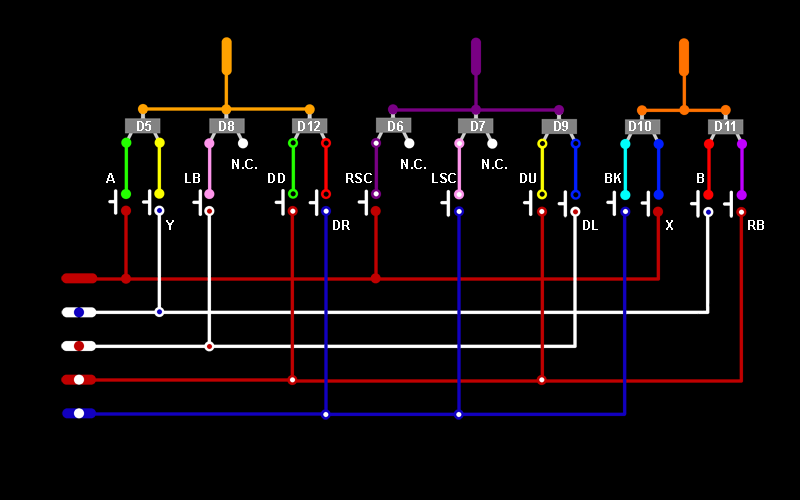
I was working with what I had handy. Sadly, the wired controller was a matrix one. I do, however, have several wireless controllers. So when I started working on the wireless version I did indeed pick a CG (common ground) version, which cut the number of wires needed in half.

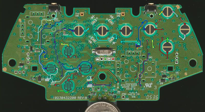
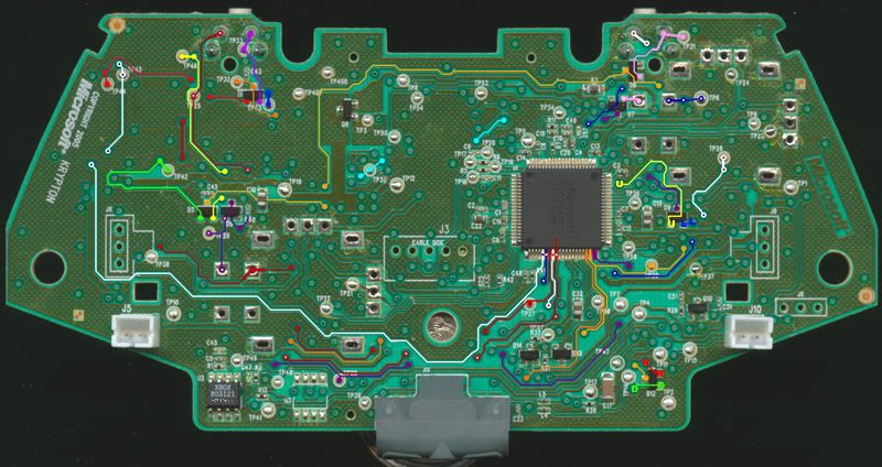
See the links in the original post to a site that has high resolution scans of the various circuit boards (with all chips/parts removed).

rboyd:
If I'm reading your post correctly, it sounds like you are currently programming the macro sequence offline. Do you have any thoughts on record/playback functionality of macros during actual gameplay? Would we need to sample the analog inputs at some frequency?

Yes. I have had thoughts about it. And, one could probably use the exact same pins/wires. However, I don't know how one would go about doing it. In the matrix configuration the voltage varied greatly between points (less than 1v to more than 3v) so it could be tricky to get a reading without interfering with the normal functionality of the controller.

However, if you were willing to gut the controller (i.e. it would no longer function normally on its own), you could permanently re-route the buttons directly to the Arduino, and then use the Arduino to send the signals to the controller PCB. There may be a little 'lag' introduced depending on how tight your sketch is. However, you would be able to see (and log) all of the button presses. Possibly having a 'record' mode and a 'playback' mode (and possibly a toggle switch for 'loop' mode). Course, that means you would need 24 inputs and 24 outputs (16 of each you skip the analog sticks), plus the buttons for record/playback/loop mode. And, at this point, the sketch required would be way beyond the scope of my skills.

rboyd:
Does a CG controller obviate the need for the optocouplers and let us use transistors? For analog inputs as well? You mentioned having some difficulty in raising the resistance for the analog inputs without messing with the existing potentiometers, but I didn't quite understand.

You could probably avoid the optocouplers with the CG setup, assuming that you really do have a common ground with both the controller and the Arduino. So, as long as you don't have the controller plugged into the console and the Arduino plugged into a transformer/wall socket you should be fine. If you are powering the Arduino from the controller (i.e. tapping into the 5v & ground from the USB), or if the Arduino is powered via battery you should be fine. But, you may want to double-check with someone more technically inclined than myself. I ended up frying a controller while 'experimenting', so I could be wrong.

Keep in mind that transistors will only save you 1 solder point per button (and there are 24 "buttons"). And, using optocouplers makes sure that the Arduino and the controller are electrically isolated from each other. So, if you should mess something up while wiring your Arduino you won't risk toasting your controller.

Lurch:
Who copied who?

Similar, but not really a copy. In my case, once programmed, the 'Arduino-controller' sits there for hours on end grinding away at a specifically repetitive task. Basically, it replaces me having to be there at all. In his case, it is 'enhancing' the users's experience/ability while playing. One of the key elements that is missing (although it could probably be added) is the ability for the script to 'wait' extended periods of time (i.e. waiting for load screens, movie clips, etc).

And, if you just wanted to do short sequences, you can use the Viking 360 Macro Controller.

Neither of those solutions would work for what I wanted to do. For example, to get the 25,000 perfect reloads in Gears of War 3 (required for the Seriously 3.0 achievement) my script did the following:

A) start the game (A button)
B) wait for game to load
C) fire 1 round (right trigger)
D) perfect reload (right bumper, wait 0.7 sec, right bumper, wait 0.5 sec)
E) repeat steps C & D for 90 seconds from step A
F) wait for the game to end (30 seconds from step A, but added a small buffer)
G) complete the game, and restart from step A

Note that due to ammo limitations step E would run out of ammo shortly before 90 seconds was up, so it isn't possible to get the 25,000 perfect reloads in a row. But one could set the the games to 2 minutes long prior to starting the script and then let the script run the hundred or so games that were needed.

Another example is racking up credits or affiliation in Forza 4:

A) select race track (A button)
B) wait 38 seconds for the map to load
C) select 'Hire driver' (d-pad down 4 times, A, A)
D) wait 12 seconds for the load
E) select 'Start Race' (d-pad up 4 times, A)
F) wait for the end of the race (depending on the track 2 to 12 minutes)
G) select 'Continue' twice (A, A)
H) select 'Continue' a couple more times just in case something leveled up (A, A, A...)
I) wait 18 seconds for menu to load
J) restart from step A

Although both the BenHeck and Viking controllers allow for 'macros', neither covers the scope that I was looking for.

winner10920:
Instead of going and switchin every button why not tap into the matric pins themself and hi-lo the approriate channel? So instead of like 15 wires, just 8 or watever the matrix is wired as

I thought that, too. But after taking some multi-meter measurements at the various points, I quickly realized that I didn't have the skills to figure it out. Someone with an electronics background could probably whip up a solution for that. Course, going with a common ground (CG) controller has the same outcome -- reducing the number of wires needed significantly. Although not nearly as few as the main matrix points.

Updates on the project...


First of all, I figured out how to get the analog sticks to work. Short the wiper pin to 'low' for full one way, and short it to 'high' for full the other way. Keep in mind that the controller does not use the full motion of the pot, so I inserted a small (220 ohm) resistor (in addition to the resistance of the optocoupler). For anyone doing this with transistors, I measured about 480 ohm at the lowest/highest points when in the enclosure by connecting the controller to a PC and using the raw calibration data from the Properties dialog. You could probably short it (I know I did once or twice while tinkering and the controller survived) but adding a small resistor (330 to 470 ohm) would make it appear more like the original pot was creating the motion. The 'low' is the ground for analog sticks on both matrix and CG controllers. The 'high' is common to ALL of the analog sticks (i.e. common high?) but is not the same as the 5v or 3.3v elsewhere on the board. So I ended up needing 1 wire for ground (already had it for the other CG buttons anyway), 1 wire for high (from one of the pot high pins), and 4 wires for the sticks (2 wipers per stick). However, you will need 8 optocouplers (or transistors?) - one to pull high and one to pull low for each wiper wire. It may be possible to use transistors to trigger the sticks since they use common ground, but I used optocouplers (since I already had them anyway).

Although I have my analog sticks wired to the PWM capable pins on the Arduino (via the optocouplers), I haven't gotten around to testing PWM yet. But, I have a hunch I will be able to generate something close to analog movement on those sticks. When I have some time I will hook up a pot to one of the Arduino analog in pins and see if I can generate the corresponding analog responses on the controller. I probably won't get around to this until I encounter an actual need for anything other than full displacements.

I also added a buzzer (so that the Arduino-controller could get my attention when a step needed my intervention), as well as a display for feedback (had some debugging issues with one of the scripts, and knowing where in the script the Arduino thought it was would have come in handy). No specific reason for the 2 digit display, other than I happened to have it laying around. The two shift registers were used to reduce the number of pins needed to drive the display.

Also, since I have a couple pins free on the controller side, I will probably end up moving the 'trigger buttons' into the controller a little below the A button (using through-hole tact switches).

In theory, I would call this a 'debug shield', and a smaller production board could be created without the display/shift registers and trigger buttons. With a little tinkering, I think I could fit the smaller "non-debug" shield entirely within the size of the battery compartment. And, if I switch over to a smaller Arduino (nano/mini?), there would be nothing sticking out. Course, with only 14 outputs, I would have to either figure out how to get 3 states out of a single pin (for the analog sticks) or skip 2 of the buttons (probably the 'click' of the analog sticks).

Now to find a case/enclosure to wrap it all up nice and neat... :wink:

HOLD THE PHONE BATMAN.

I did a similar project to this and I would love to know more details on what you did. I took the PCB of the controller, unsoldered the triggers and joysticks and then I connected digital potentiometers to replace them. It worked flawlessly with controlled input.

That being said, my buttons were nightmares. I used an exacto knife to scrape the trace and solder to that tiny tiny piece with enameled wire. It was terrible and unstable. How are you handling your connection to the buttons? I think this project is great and glad someone else has a similar interest!

nintendo9713:
I did a similar project to this and I would love to know more details on what you did. I took the PCB of the controller, unsoldered the triggers and joysticks and then I connected digital potentiometers to replace them. It worked flawlessly with controlled input.

I had never heard of digital potentiometers until I read your post. Did some Google-ing and am quite intrigued. Obviously I don't have any laying around my workshop... If it turns out that PWM doesn't work and I really need an analog pot situation, I will have to go out and buy a couple. Thanks for the heads up.

nintendo9713:
That being said, my buttons were nightmares. I used an exacto knife to scrape the trace and solder to that tiny tiny piece with enameled wire. It was terrible and unstable. How are you handling your connection to the buttons?

Agreed. That was the hardest part of the 'wireless' version of the project.

The wired 'matrix' controller (and possibly the wired CG one, too) has test points for every button in question, so that was easy to solder up (although I did have to remove the triggers to get at a couple of them). And, if it hadn't been for the success with the 'wired' version of the project (albeit double the wires), I probably would have given up.

The wireless controllers (all of them based on my research) don't have any easy to get at points for the buttons (except d-pad right -- TP9). The rest of them were indeed the pass-through points, many of which were only accessible from one side and required the removal of the triggers, etc. I had a real hard time with the first controller. I just could not get the solder to stick on a couple of the points, even after I had carefully scraped off what I deemed was more then enough of the 'paint'. I ended up setting that controller aside (it still works normally, for now, but I had to re-wire one of the d-pads directly to the chip -- ugh), and moved on to a second. By then I had determined that I could carefully (and I mean VERY carefully) use a cordless Dremel with a fine metal 'ball' tip. I was able to get a nice copper shine with just a few very light passes (a vice and support for both forearms is highly suggested). Then, I cleaned the points with isopropyl alcohol, applied a little flux, lightly wiped off any excess flux and was able to put down itsy bitsy solder points. Finally, I pre-tinned my [28 AWG?] hook up wire (no idea how I ended up with a spool of it), snipped off the excess wire after the insulation shrank, and attached them to my solder points. I was able to insert the wires about half the depth of the circuit board, effectively making little 'hooks' on the ends. Since those points are undoubtedly fragile, I made sure the wire was already mostly bent along the final path it would have to take before soldering it down, and immediately pinned it at several points, initially with masking tape strips, and finally with a dab of hot glue here and there (usually a couple wires running next to each other at a time). All of the wires were tracked back to one of the rumble pack spaces (permanently removed) and zip-tied into a nice little bundle so that no one wire gets tugged on when I move things around.

If I was anywhere near as confident as that paragraph may sound, I would open up the controller and take some pics for ya... But, I will be the first to admit that I am afraid the simple act of opening the case one too many times could cause one of those flimsy solder points to pull off, possibly even pulling the tiny coper ring (which I may have ground down to almost nothing), would pop off, too, wrecking the controller completely. So sorry.

If I am ever going to prep another controller for this project, it will be a wired CG (I will have to go and buy one though). Since I doubt I will ever run my scripts wirelessly due to battery concerns, I really don't know why I bothered with the wireless controller in the first place. I just happened to have a few of them laying around, so that is what I used. But, I won't do that again.

I was helping another forum member in this post with the same thing you want. He wants a macro ability to take panorama shots in halo reach. He said for his buttons he used fine grit sand paper to remove the coating on the button pads which gives him a much bigger solder joint. I did enameled wire and hot glue, which is similar to yours.

I removed the sticks and triggers from mine, I just want the board, so with that being said, I would love to find a version of a controller that has ample test points for buttons and sticks. I'll look into the Matrix model you described and see. I'm using a wireless CG model.

In the above post, it shows where to order the digital potentiometers for free (University or work email), and how I used them so give it a read and feel free to ask questions!

nintendo9713:
I was helping another forum member in this post with the same thing you want. He wants a macro ability to take panorama shots in halo reach. He said for his buttons he used fine grit sand paper to remove the coating on the button pads which gives him a much bigger solder joint. I did enameled wire and hot glue, which is similar to yours.

Interesting read. I found the reference to the CD4066B (quad bilateral switch) worth looking into aswell. Although it is only 2 wires less per DIP, it could be an alternative if I run out of optocouplers.

nintendo9713:
I removed the sticks and triggers from mine, I just want the board, so with that being said, I would love to find a version of a controller that has ample test points for buttons and sticks. I'll look into the Matrix model you described and see. I'm using a wireless CG model.

I think that both of the wired models will have the test points for everything you need. But I don't think there is a way to differentiate the two wired controllers without cracking them open. Here is a link to a thread that has scans of the various controller PCBs: http://forums.xbox-scene.com/index.php?showtopic=660109

nintendo9713:
In the above post, it shows where to order the digital potentiometers for free (University or work email), and how I used them so give it a read and feel free to ask questions!

I am looking over the digital potentiometers list now. Lots of interesting stuff there. Sadly, not many DIP. And, I don't have a way to mount TSSOP/SOIC. :~