I recently purchased a plotter from Aliexpress and despite being promised instructions it came with none. The seller is worse than useless and refuses to help. Lesson learned there.
Anyway I’ve managed to put it together somehow but the problem i have is with connecting the three stepper motors to the circuit board. I may be asking the impossible here but maybe someone could help me turn this lump of metal into a functioning plotter/drawer.
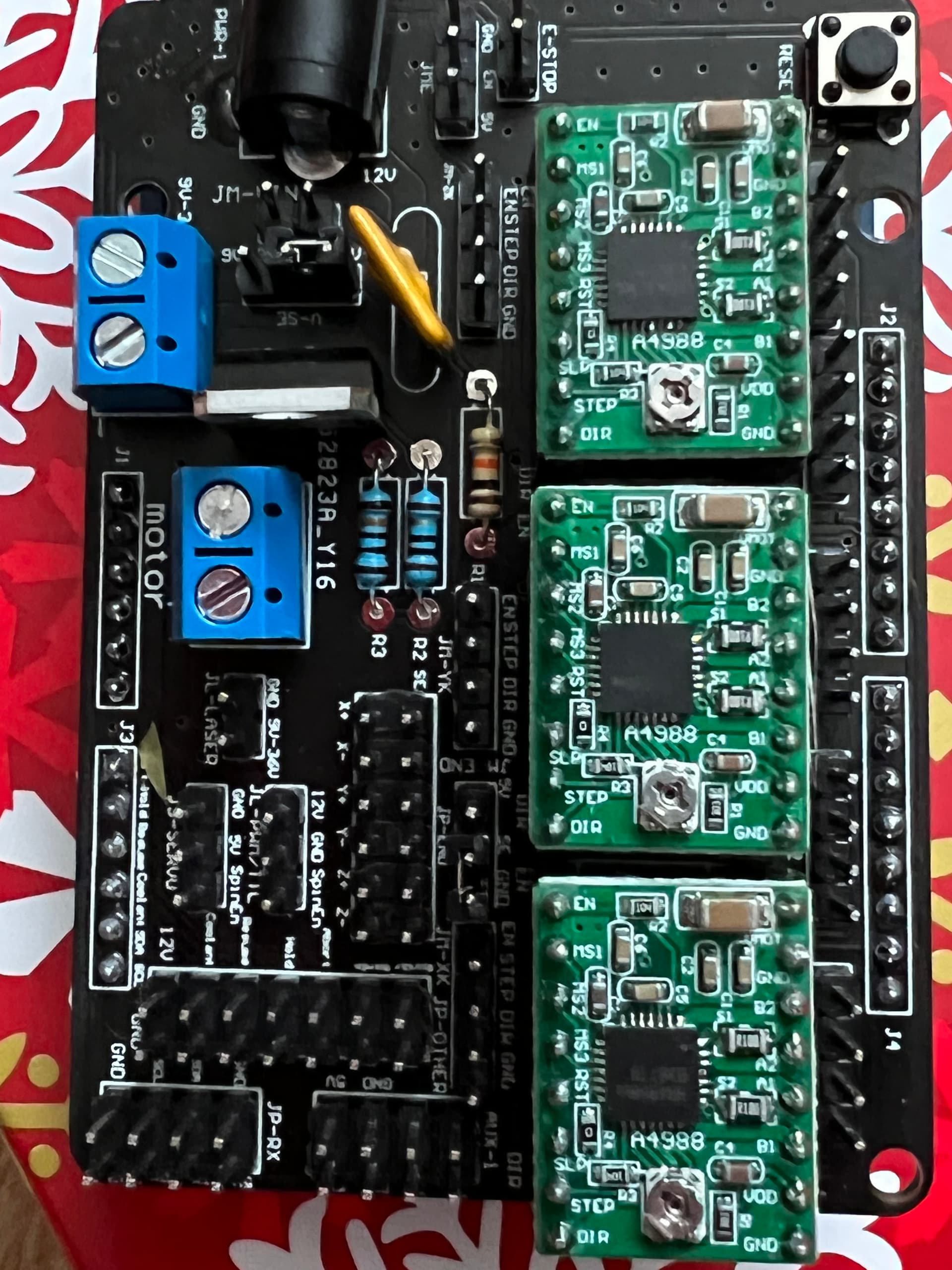
Very important to make sure the stepper motor driver boards are inserted in the correct orientation - you do not want those to be turned 180 degrees.
If I recall correctly from 3D printers, the stepper motor connectors themselves are usually wired so that they can be inserted either way, turning the plug around reverses the direction of the motor. Good idea to check the direction of rotation before putting the belts onto the motors.
I'm sure there are XY plotter forums (or at least 3D printer forums), if you can post a picture of the control board on one of those you will likely find someone familiar with it. Highly likely that board is a clone of an open-source design.
@davels did your board come with these driver boards already installed or did you fit them yourself?
From your photo, the base board looks to be fairly easy to follow the various tracks to see where they go to/from.
If you google "A4988 Arduino", you will find lots of examples of how to connect a stepper motor to these driver boards. Interesting (or worrying?) that some show a heatsink on the actual driver chip on these boards, whilst others don't.
You should be able to visually trace the tracks coming from the 1A, 1B, 2A & 2B pins on the driver boards. Which connectors do they go to?
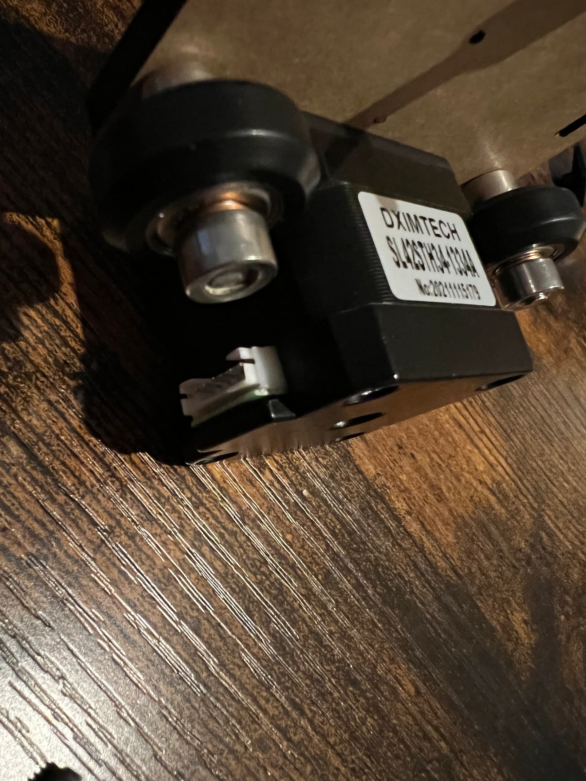
What cables do you have coming from the motors & end stops?
I assume that there are 4 wires coming from each stepper. Are they terminated in a made up connector? What about the end-stop switches? Are they terminated too? If they are, does that help you narrow down where they should be plugged into this board.
Are there any clues on the other side of the board?
I've never seen the specific board you are using, the only one I've used is the ramps board for a 3D printer. There are lots of warnings with the ramps boards to be sure you do not install the stepper drives rotated 180 degrees. The stepper motors I had were already wired with connectors, the wiring on those was arranged so that rotating the motor wiring connector 180 degrees would reverse the direction of the motor.
Would be a very good idea to have a multimeter, you will need it if you want to correctly adjust the current limit on the stepper motor drivers.
I can clearly see a made up 4 pin connector and a made up 6 pin connector in the photo, plus others behind. If you spread those cables out, rather than the nicely shipped bundle, which ones go where on your motors & limit switches?
Looking at the photo of the rear of the board, I can possibly make out where the motor A & B tracks go. They appear to go to 4-pin male connectors next to J2 & J4. Does each motor have a cable that ends in one of those white 4 pin connectors?
Yes sorry, there are three cables and they each have a six pin on one end (to motor) and four pin the other (to circuit board)
The six pin only fits one way into the motor. Two motors control the X and the Y and the other motor lifts and drops the pen. There are only three cables.
Well that kinda narrows it down. I guess that there are no limit switches on the mechanical frame?
You need to visually check this yourself as you have the board in your hands, but from the photos, it looks like those 4 pin connectors plug in to those 4-pin male headers below the reset button.
From what I can tell from the photos, ignore the first 4-pin male header (by the mounting hole), a motor cable then plugs into the next 4-pin male header (next to where the silkscreen printing says J2) , then skip a header, then motor #2. As for motor #3, I can't see where that plugs in. You should be able to follow the tracks on the board to the connector. You may have to remove the driver board if the tracks are on the top.
There are no limit switches at all, I suppose that’s another issue I will have to face when I eventually get it built with the software. If I can find it, the seller has not provided software either, it’s a bit of a mess.
I’m at least a little further on in my mission thanks to your help, which is much appreciated.
Yes, that's where I think 2 of the motor cables go. I would probably just connect up one of them for now.
Next step is to figure out what signals are used on the pins that connect your board to the UNO. This website has some useful information on the A4988 driver board. It tells you what each pin on the board does. You should be able to determine where those pins on the left hand side of the A4988 driver board go. The STEP & DIR pins will go to the UNO via one of the 3 connectors (the 4th is the power pins on the UNO) as they are used to make the motor move.
Just a thought, and it may not get you any further forward, but there a several sellers of CNC shields for Arduino UNO. They all seem to sell the same board with yellow headers for the motor drive boards. If you do a search for "CNC Shield V3" you should get plenty of hits.
There's one (probably more!) here in the UK sold by Hobby Components. Follow the link and you will see.
The board itself is very cheap - because it doesn't include the motor drive boards. But guess what - you already have them!
You may make a lot more progress using this board as there is likely to be plenty of web sites and youtube videos about setups using it.