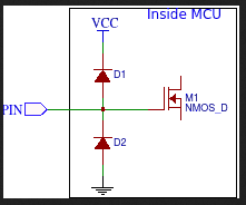
I would like to use zener diodes to protect the MCU GPIO pins when driving MOSFETs directly. Is the HZ5C2 a reasonable choice for this? I would prefer the HZ5C3 because I don't like wasting precious electrons or gate potential down the zener unnecessarily but the HZ5C2 is more readily available.
It is unusual to protect an output pin using a zener diode in that configuration.
What risk do you see ? A drain to gate short circuit in your mosfet ?
On that page in section 3, it's moved before the resistor. I thought this would be better because then that resistor limits the current through the diode in the event of a drain-to-gate short. The reason for the zener in the video isn't explained but I figured it might be due to some induced voltage that happens when the MOSFET starts conducting? He just says in the video "occuring overvoltages" and doesn't explain how they might be generated. If a MOSFET does fail closed, I would like the microcontroller to be protected though.
Is it not possible for the gate to short circuit to the drain, delivering 12 V to the MCU that way? I would like the MCU to be protected in the event a MOSFET fails e.g. due to ESD damage.
Not again...
This comes up very frequently.
Zeners can't protect MCU pins, because max pin voltage is not always 5volt.
Be skeptical about all advice given on internet pages that you can't correct or comment on without joining and logging in. Yes, that Designspark page has errors.
If you would need to protect that circuit from post#1, then use a Schottky diode from pin to VCC of the Arduino, instead of the useless zener.
The 10k resistor should go on the other side of the 200 ohm resistor (between pin and ground).
Not that it makes a lot of difference.
Leo..
No. He means that the maximum allowable voltage on an IO pin is Vcc+0.5V. This is clearly stated in the data sheet, which you should read at some point. Then you will be better equipped to understand what we are trying to tell you.
If Vcc is zero, that means the maximum allowable voltage on an IO pin is 0.5V
I'm already aware that the max allowable GPIO voltage is VCC + 0.5 V. Knowing these facts is one thing; it's another to put them all together and extrapolate a conclusion like what scenario a Schottky to VCC makes sense, especially when it's different from the scenario I was talking about originally.
If I put a Schottky diode leading to VCC and the MOSFET fails shorted between gate and drain with no zener to stop it going higher, then the VCC is 12 V and the MCU dies anyway? So I guess I'll keep looking at optocouplers.
Yes, or 0 volt when the Arduino is off.
Then max pin voltage is 0.3volt, and the zener does nothing.
Now it also is a voltage divider, reducing gate drive voltage about 2%.
You don't have that if the resistor is on the other side. Read this.
It dumps over-voltage on the supply of the Arduino.
Pin can never be more than 0.3volt higher than the supply, whatever supply voltage is.
Google "clamping diode" (images).
Leo..
Okay, thanks but I think the Schottky alone would also not help if the voltage was 12 V; it would just deliver that to VCC and break the MCU anyway? I could understand if the argument was that the zener and Shottky could work together. I'm not actualy expecting the MCU to be off when the MOSFET drain is high because the 12 V will also be going to the voltage regulator for the MCU. A broken connection or damaged regulator could do it.
But there is a 200 ohm resistor in between, that reduces current to (12-5) / 200 = 35mA.
Hopefully to less than what the Arduino itself consumes (The Uno draws 50mA).
If fault current could be more, then a 5volt (standoff) TVS diode (super-zener) across the 5volt supply of the Arduino would be more sensible than a 5volt zener from pin to ground.
Leo..
It looks like the 5 V stand-off TVS diodes don't start conducting much until the maximum MCU supply voltage has already been exceeded although I realise there may be some margin above the maximum before damage occurs. If I use H11L1 optocouplers, I can increase the MOSFET driving current a little bit and increase the driving voltage to 12 V.