I have to agree with @sterretje here - the DS3231 has an isolated battery input which is specifically designed to keep the internal clock (not the I/O pins) alive when Vcc is gone. If you turn that diode around, your battery will be trying to drive Vcc (at around 2.3ish volts) and potentially an entire system connected to it (not just the power LED!). The resistor/diode combination really just looks like an extremely badly-designed charging circuit, or a circuit designed to charge a supercap (which should actually work quite well). So either use a supercap (would be nice if a supercap was available in a CR2032 form factor!) or disconnect that circuit to avoid a nasty fire/explosion.
3 Likes
So i just recieved two rtc with cr2032 batteries in them. I order may 8, so they are still shipping them.
This is from the ebay page, note they state the battery cr2032 is rechargeable. or is it poor wording and they are trying to say the circuit will stay working with the battery "recharging the cuircuit"
Description:
1 Size: 38mm (length) * 22mm (W) * 14mm (height)
2 Weight: 8g
3 Operating voltage :3.3 - 5 .5 V
4 clock chip: high-precision clock chip DS3231
5 Clock Accuracy :0-40 ℃ range, the accuracy 2ppm, the error was about 1 minute
6 calendar alarm clock with two
7 programmable square-wave output
8 Real time clock generator seconds, minutes, hours, day, date, month and year timing and provide valid until the year 2100 leap year compensation
9 chip temperature sensor comes with an accuracy of ± 3 ℃
10 memory chips: AT24C32 (storage capacity 32K)
11.IIC bus interface, the maximum transmission speed of 400KHz (working voltage of 5V)
12 can be cascaded with other IIC device, 24C32 addresses can be shorted A0/A1/A2 modify default address is 0x57
13 with rechargeable battery CR2032, to ensure the system after power failure, the clock move any natural normal
14 Packing: single anti-static packaging
Wiring instructions (with Arduino uno r3 for example):
SCL → A5
SDA → A4
VCC → 5V
GND → GND
So I am just learning and thats why i look everything up, i have read different "solutions" to the problem and understand that charging a lithium (I just learned the lithium = non rechargeable and lithium-ion = rechargeable) battery is a bad thing. so what is the simplest way to stop this from happening?
Of all the things i thought I would get hung up on... the battery lol
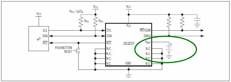
Reply #1 has an image of the board with an indication which track to cut for use with CR2032; it also has the schematic.
If you have a soldering iron, you can remove the resistor just above the word SCL at the right or the diode (next to the bigger chip).
From the schematic you can see that any of the above will break the path between Vcc and the battery (BAT)
I have done neither of these exercises yet.
SpoodleMix:
If you are wondering if I will ever get to the point (solution), here it is. The diode is in backwards. That is it.The diode's only function is to block charging of the CR2032 from power off of VCC, not provide a charging circuit. The resistor is a current limiting resistor intended to take the load off of the diode.
The battery should provide power to VCC to keep the RTC running in case of a power failure. This is a one way job from the battery to VCC. The way the board is shipped from China, makes a power path from VCC to the battery, not the other way around.
If you reverse the diode, you will have full functionality of the RTC, including battery backup. Only problem is that the power LED will drain the battery quickly. If you want to remove or cut anything, reverse the diode and then remove the LED so your battery will last longer when the system power is off. Remember, just because someone manufactured it, it does not make it correct. This board is both a bad design along with bad manufacturing. But does work if you fix it.
I agree with the above explanation of SpoodleMix.
Someone thinks, I will be smart and has changed it without enough knowledge of electronics and batteries.
He thinks...., if the battery is empty, I lost the time setting.
Okay, I will use an LR2032 (chargeable battery) connect it to Vcc by a diode and resistor and it will be charged all the time.....
(As you can read in story of MrAl, that kind of battery needs an special charging circuit and not this simple one...)
Based on this thought before, the print layout was changed but still the wrong battery CR2032 (not chargeable) will be delivered.....) After a time, it explodes....
Read this also; The right RTC battery… – WoodUino.ca
THE BATTERY CR2032 SHOULD ONLY BE CONNECTED TO Vbat OF THE DS3231 AND NOTHING ELSE!
The correct solution is; (1000% SURE)
Connect battery CR2032 directly to Vbat of DS3231, remove diode and/or resistor and problem is solved.
Power consumption of DS3231 is very low so the time will run well for many years.

Melancho:
The correct solution is; (1000% SURE)Connect battery CR2032 directly to Vbat of DS3231, remove diode and/or resistor and problem is solved.
Power consumption of DS3231 is very low so the time will run well for many years.
That is not what Spoodlemix suggested. He / she stated that the battery should feed the Vcc via a diode, not Vbat.
By the way, the battery is already directly connected to Vbat.
2 Likes
Disclaimer "I am a newbie" but I was concerned about this very issue as I ordered a RTC and it said lir2032 but came with a CR2032. I checked with a volt meter and there is about 4.75V @ 20 ma going to the battery. I looked at one spec sheet for the LIR2032 and it says
"Constant Charging Method Constant voltage 4.20V Constant current:17mA"
So my question is is 4.75 @ 20 ma close enough?
is 4.75 @ 20 ma bad for a non rechargeable battery?
Also the voltage is going to one pin on an ic when the main power is cut .. even before the diode stops it so I would venture to say the clock will keep its time from the battery when main power is out as it should.
Comm64:
is 4.75 @ 20 ma bad for a non rechargeable battery?
Quite sure it is; see opening post and reply @. Charge at your own risk.
Comm64:
Also the voltage is going to one pin on an ic when the main power is cut .. even before the diode stops it so I would venture to say the clock will keep its time from the battery when main power is out as it should.
Correct.
Glad to see that this thread is still alive, as I had a clarification question.
Reading through the above responses, people seem to have mixed opinions about 5V power and an LIR2032 battery. Currently, my DS3231 is connected to the 3.3V, but I've noticed that after leaving it powered for a few days, the LIR2032 has no charge. As soon as the RTC module is unplugged, the battery does nothing and it's dead.
Is there anyone that can give me a definitive answer as to whether it is safe to charge the LIR2032 using the 5V power supply? Because if I can't charge it using that, and I can't charge it using the 3.3V, then I don't really know any other way to charge it...
Thanks!
I can't answer that; I'm planning to use the non-rechargeable CR2032 and modify the circuit.
Do you really need a rechargeable battery? The battery will only power the RTC chip if it is not powered from Vcc. So I suspect a CR2032 to last a very long time in a permanently powered setup.
I guess I don't need a rechargeable battery. The thing is, I need the RTC for an LED setup, and the whole thing is unplugged every night. How many nights does a non-rechargeable battery last for?
My other issue is I'm not really comfortable enough with electronics to mess around with the RTC module itself. I'm just afraid of screwing it up.
With my interpretation of the RTC spec: If powered down, the RTC draws 3 uA from the battery. The battery can deliver 210mAh; that would give 210mAh / 3uA = 70000 hours.
Found a post somewhere on the web: http://forum.allaboutcircuits.com/threads/rtc-battery-backup.80592/#post-572321; states 5 to 10 years and matches more or less my interpretation / calculation.
Jeez, some have the info right, others claim dangerous BS.
The "charging circuit" is really evil. The battery is otherwise connected correctly.
See the schematics here:

Remove the 1N4148 and/or the 200R resistor and everything is fine.
I also removed the power LED as I use the RTC for a DIY clock. Works great this way with 3.3V supply.
 (click for bigger image)
1 Like
Koepi:
Jeez, some have the info right, others claim dangerous BS.The "charging circuit" is really evil. The battery is otherwise connected correctly.
See the schematics here:Remove the 1N4148 and/or the 200R resistor and everything is fine.
I also removed the power LED as I use the RTC for a DIY clock. Works great this way with 3.3V supply.
(click for bigger image)
So... Dumb question... How do I remove the battery that I currently have in the module? I've got an LIR2032 in there and it's a pretty tight fit, not really much room for me to stick something underneath to pry it out. Also, the battery should go in with the negative terminal facing down and positive facing up, is that correct?
EDIT: So I figured out how to remove the LIR2032 and replaced it with a CR2032 I bought on amazon... The LED did not light up. I'm assuming that the LED should be lit when it is powered via the battery, and I probably ended up with a bad batch of batteries...?
I'm assuming that the LED should be lit when it is powered via the battery, and I probably ended up with a bad batch of batteries...?
Your assumption is incorrect! As mentioned in a previous post the purpose of the battery is to keep the internal timekeeping functions running when the power is removed from the module.
Don
1 Like
joshjayk:
EDIT: So I figured out how to remove the LIR2032 and replaced it with a CR2032 I bought on amazon... The LED did not light up. I'm assuming that the LED should be lit when it is powered via the battery, and I probably ended up with a bad batch of batteries...?
Ah, you want the battery to only last 210mAh / (e.g.) 10mA equals 21 hours ![]()
floresta:
Your assumption is incorrect! As mentioned in a previous post the purpose of the battery is to keep the internal timekeeping functions running when the power is removed from the module.Don
Yeah I realized it was still working without the LED lit!
sterretje:
Ah, you want the battery to only last 210mAh / (e.g.) 10mA equals 21 hours
What do you mean? You mean the batteries I got from Amazon are bad?
No, if the battery would power the LED as well, it will have a very short life.
Many interesting comments here on the ZS-042 RTC module. For the most part, this is a great module and very reasonably priced. I was asked to address an issue with this RTC for a high school science project.
These issues are common with most ZS-042 modules.
Battery swells up after a few days of use. This is true for the LIR2032 and the CR2032 when the module
is supplied with 5V. If supplied with 3.3V, the LIR2032 will not receive a charge due to low voltage and the CR2032 still receives over voltage to its terminals. This excess voltage is coming from the DS3231 IC.
As stated many times in previous posts, the charging circuit on this module is very poorly designed and should
be disabled by removing either the diode or resistor in the charging path. The LIR2032 should be replaced with a CR2032. Swelled CR2032's must be replaced before case failure occurs.
After this, one problem still remains. If you look at the voltage on the CR2032, when connected to 5V or 3.3V
supply, it will have about 3.3 volts at the terminals. This is not good for the CR2032 and should be addressed.
If you supply 3.3V to the RTC module through a simple diode, the voltage will be reduced to about 2.75V. This
is within spec for the DS3231 and will prevent excess voltage going to the CR2032 battery. Not all modules have this problem but most do.
These changes have been made to dozens of projects without issue. The school continues to purchase this module for their labs and makes the simple changes before distribution to the students.
These design flawed ZS-042 modules are now selling on eBay from sellers in China for as little as $0.75USD, including shipping charges to USA.
All that's needed to fix these is just to remove the 200 ohm surface mounted resistor marked '201'.
I did confirm what robertew was saying about excessive voltage on the coin cell, but couldn't confirm what he said about higher voltages on the coin cell after disabling the charging circuit. I measured cell voltages both before and after removing the charging resistor.
Before:
Vcc CR2032
0.0v 3.18v - -
3.3v 3.22v
5.0v 3.34v
After:
Vcc CR2032
0.0v 3.18v
3.3v 3.18v
5.0v 3.18v
I also tested the modules I2C serial on both 5.0v and 3.3v Arduinos. Both Arduinos tested good with modules Vcc pin powered by either 5.0v or 3.3v. >>> Warning: 3.3v Arduino board processor input pins may be damaged by connecting them to 5v powered sensors. So, supply the DS3231's module's Vcc with a supply voltage consistent with the Arduino processor's supply voltage. <<<
Hi. I read the previous posts on the ZS-042 RTC board. New here but experienced with electronics.
First off, if you have a CR2032 (non-rechargeable!), by all means, don't put it to work with the board as is. REMOVE the diode or the "201" resistor first, or cut the copper trace between those two. This will ensure the battery won't try to charge and possibly explode.
If you have the LIR2032 (rechargeable) or want to use one, read on...
My experience:
My board came with a LIR2032 rechargeable battery and I've been using it for several months now without any problems. No swelling or such. Also, the battery works great in supporting the DS3231 IC's timekeeping whenever external supply is removed.
My suggestion:
If you have the LIR2032 rechargeable battery on, just leave the ZS-042 board alone. The already installed 1N4148 diode drops the 5V voltage to 4.3V and that is around the maximum voltage your rechargeable battery will ever get (and can take) while charging, plus the 200 ohm series resistor makes sure the charging current is very low.
[ I=(4.3-Vb)/200 (Amps), where Vb is the voltage between the battery poles; will go up to 4.2 V as batt becomes fully charged.]
P.S. If you are the kind of people that want to be extra safe, and feel comfortable and experienced with electronics, you can try connecting a low forward voltage diode (schottky would do) in series with the already installed diode. That will drop the charging voltage around 0.2 V further down. The battery will now end-charge to a less-than-full condition, but will still be fine for keeping the RTC ticking during mains power failures.