Hi,
I have 8 AEG Evyn LED RGB ceiling lights and they come with a RGB led strip around the light.
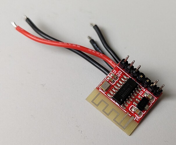
These lamps come with a proprietary 2.4GH RF controller with a matching remote control.
This controller is a little PCB that is mounted in the 24V LED driver.
Of course I wanted to get rid of this as soon as possible ![]()
This controller is powered by 12V and sends out 5 times a 3.3V PWM signal to drive CC, CW, R, G and B to the 24V LED driver. I have tested and played with this and in the meantime successfully connected a IKEA Tradfri Zigbee controller, with it's 3.3V PWM signal to the CC CW channels.
It's hanging on my ceiling now and I'm controlling this with Zigbee2MQTT.
Now in my office I want to hang up 8 of these lamps and my idea was to control the RGB LED strip in them with 8 WS2411 modules. Most importantly so I can use WLED with all it's awesome effects but also because it's a one-wired signal.
The reason that I chose the WS2411 is because it says it uses PWM to drive the 3 RGB channels.
I bought a few WS2811 breakout boards:
I have done some testing for myself (still in the learning curve of electronics) and hooked up 4 of these WS2811 breakout boards including some standard RGB LEDs to my ESP32 WROOM and everything is working great.
What I have figured out (and should have know before of course) are a few things:
-
The voltage that the separate channels get is between 2V and 3V (2.7V to be exact for the Green LED at full power), because a LED on average needs around 2.5V. This is of course is not enough voltage for a 3.3V PWM signal.
-
For this WS2811 module you need to buy RGB LEDs with a common anode. That means that the shared pin on the RGB led gets a positive voltage (5V in this case) and the 3 other RGB pins get a PWM signal that is pulled to/connected GND (ground).
A standard clean 3.3V PWM signal most often has the positive PWM channel from 0 to 3.3V.
In this case the 24V controller on the AEG Evyn light also need a positive PWM signal for the R, G and B channels.
My question now is of course how to get this to work?
-
I probably at least need a level shifter to shift the outgoing 2-3v to 3.3V. Also I probably need to add a resistor between the output of the WS2811 and the level shifter, because the output is around 18mA at full brightness, and that maybe is too much current for the level shifter.
-
I need to somehow reverse the voltage of the (negative) PWM signal, so the output to the 24V LED controller is between a (positive) 0 to 3.3V.
Or... Could there be a better way? Maybe by using a Optocoupler with some resistor (what value) between it and a fairly simple circuit behind it with some transistor?
Or... should I ditch the whole idea with the WS2811 and connect these 8 lights to my ESP32 WROOM somehow in a different way (direct PWM from ESP32?)?
Most importantly is that I definitely want to use WLED for these 8 RGB lights. I also like to use a one-wire signal to the light. And lastly it would be great that I can mostly use ready made modules, because that's more easy then to make 8 custom made circuits between the WS2811 and the 24V LED driver (however that will positive for my learning curve)
[It's awesome that you read this far ![]() ]
]


