hello all, hope everyone is having fun with projects.
looking online - i found following design for schematic.
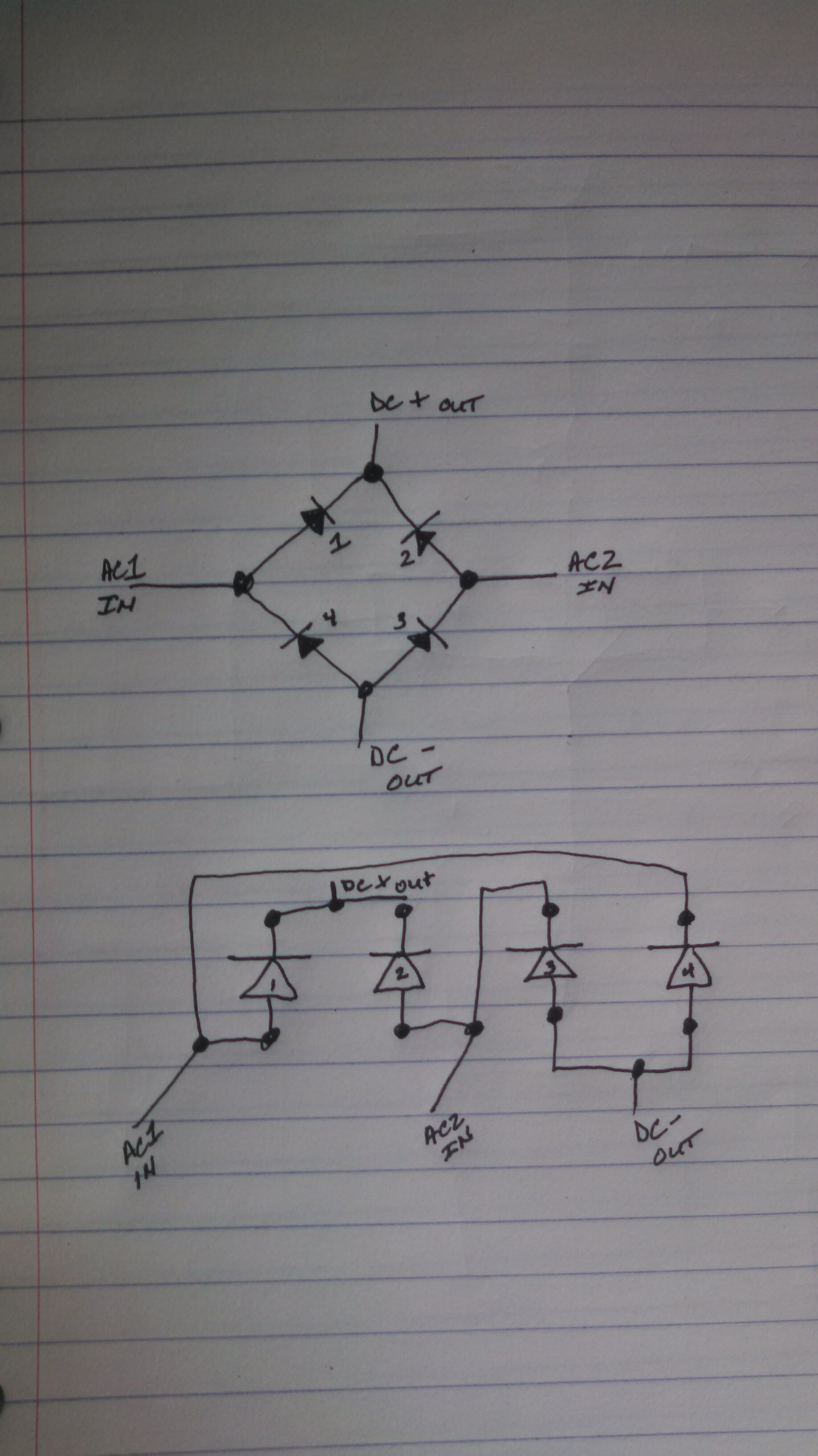
i did rough hand sketch of actual diode layout.
i want to make a library entry in eagle cad to use. i have not been able to find one for 4 diode layout.
i want to use diodes since i have a crap load ( just under a SH!! load LOL) and i dont want to spend more money just yet on actual bridges.
now, if i may ask y'all, the sketch i did for pcb layout (bottom):
1.) is it correct by looking at points from top image???
2.) when using wall wart with ac, i kow converts to dc, does it have any affect on dc input, beside v-drop???
3.) when selecting 4 diodes, does the rating go by individual or pairs? say to get 2A bridge rating?
You're supposed to assume the current that enters the bridge also is leaving the brigde.
There will be 2 diodes active at any given time the AC is present.
Current rating is per diode.
originally i was thinking pairs since the output goes through basically two diodes
but now that you say that and looking at diagram. there is only one diode per input for the output either side.
is there any short or long term effects from using dc input also? i have pcb that i will be using with wart as well as in car.
No, there shouldn't be any problem supplying that with AC or DC, long term. The only thing to keep in mind, besides the fact that you lose 1.4V either way, is that 12Vdc nets you 11.6Vdc, but 12Vac nets you 12Vx1.414 - 1.4V = 15.6V.
Because 12Vac is about 17V peak, and the capacitors after the bridge charge to the peak voltage.
That is an electron microscope image of a piece of paper. I cropped that out of your original image. Heh, heh....
Actually, the current rating for a bridge rectifier when rectifying AC is 1.5 (perhaps 2) times that of a single diode because the two pairs are sharing the load over each cycle.
aes92000:
i did rough hand sketch of actual diode layout.
i want to make a library entry in eagle cad to use. i have not been able to find one for 4 diode layout.
Eagle library entries are single devices, not groups.
of course eagle has by default a rectifier in it's libraries (for schematic as well as different footprints for layout). To be more precise: there is a dedicated library only for this kind of parts (rectifier.lbr) which is by default part of the Eagle distribution.