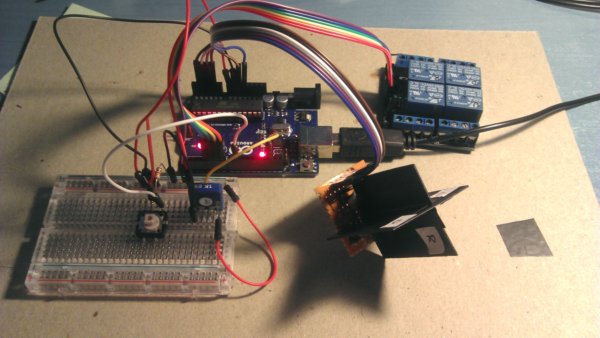
I am building a 2 axis solar tracker. In order to measure light intensity I am using 4 LDRs (up, down, left, right). Light sensing part is built on an independent stripboard (my future intention is placing this part on the front of the panel and Arduino on the back to protect it from direct sun exposure).
Program and circuitry seem to be working well, but when I point to an even light source, readings from the 4 LDRs are not the same. To be sure that light is even on the 4 LDR, I surround sensing piece with white cardboard and then I use a white area on my LCD monitor as light source.
On my code, I take several measures from each LDR and average them, to remove noisy readings. Unfortunately, readings keep being different.
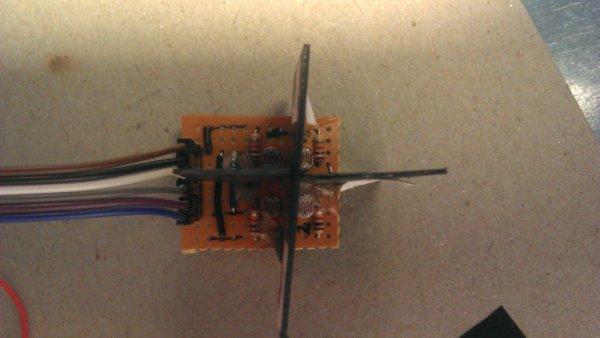
4 LDRs (2-axis)
Light readings. Notice cardboard to avoid other light reaching LDRs. On the screen, the number of "U,D,L,R" is proportional to light reading (kind of bar graph). Number at the end of line is analog reading (0-1023).
Has anyone experience designing this kind of solar tracker?
Can the problem be originated by the components themselves?
How can be this problem worked out in order to have a precise sun tracking?
Components, in data sheet for LDR what I have, distribution area on log scale covering 50 - 300 (left side fig.3), it's about 600%. You can easily trim sensitivity in software, setting different thresholds. Or, make the separator planes longer, to increase angular resolution
I have tried a correction. By means of a pushbutton you can tell the arduino to calibrate LDRs. You must be pointing to an even light (such as the white LCD area).
The problem is that this coefficients level measurings at one light level, but if afterwards I measure another even light weaker o brighter, readings are not leveled.
Can anybody suggest another correction method more advanced?
Are you sure that you need high precision? LDR isn't desigh to be accurate, you may approximate each of the sensor individually using higher degree polynomial, let say now you have half of one (first degree should be a * x + b, where b is offset and "a" is slope). I have a project where I used 2-nd degree approximation, all coeff. calculated by arduino, all you have to do is set 10 pre-defined levels (in your case brightness, in my frequencies) .
Have a look, least squares method: http://coolarduino.wordpress.com/2012/10/23/diy-arduino-fm-radio-part-2/
As you probably, don't have calibrated lux meter, I'm not sure if would work right with your monitor brightness percentage scale, which is quite approximate itself AFAIK. Secondly, check how LDR affected by temperature variation.
Photodiodes , may be better choice , easier to get accurate results.
You are using a multiplication factor on what I assume is the direct ADC reading (0 - 1023). This is proportional to the way you have configured your voltage divider. An alternative correction would be to assume the sensitivities of the different LDR's are the same, but there are constant factor offsets between the different LDR resistance values. This method is a bit more involved since it requires you to convert the ADC reading into the corresponding LDR resistance. If I assume you have configured your voltage divider as follows: Vcc - LDR - measuring point - fixed resistor - ground then your ADC reading would be related to the LDR resistance as follows:
ADC reading = R_fixed / (R_LDR + R_fixed) * 1023
It then follows that a fixed percentage offset of the LDR resistance would lead to a non-constant percentage change in the ADC reading. To assign a constant calibration factor to the LDRs you have to convert the ADC reading back to a resistance, then apply a correction factor, e.g.:
R_LDR = (R_fixed*1023 /(ADC reading) - R_fixed) * correction_factor
Of course if you do this your control logic will have to reverse, since the R_LDR and ADC values are inversely proportional. Or you have to convert your corrected R_LDR back to a corrected ADC reading, but this is unnecessary in my opinion.
Further, it seems as if your fixed resistors are of 5% tolerance, this may also contribute to different voltage divider ratios if the different resistors have noticeably different values.
Thank you for your comments. I am reordering my code and trying to incorporate some of them. I still don't know how much solar panel aiming will be affected by these lack of precission, but I suppose that it will not be serious. Using 1% tolerance resistors will be a must on my definitive version.
I will report my results when I have all the components assembled.
Taking light from an led/lcd screen is not optimal nor is incandescent light, try using a globe (pearl) or direct sunlight, where the sun is a magnitude greater in diameter.
I use ldr too, parallel/series affects resistance, with their own rail & proper grounding will eliminate a great deal of "Weirdness".