I am having a hard time getting RadioHead Library with the (RH_ASK Class) to change from its default pin parameters. RadioHead states that Pin 12 is default for Tx and 11 is default for Rx, but I need to change Rx to pin 10.
I am using arduino nano and a cheap set of 433MHz Transmitter and Receiver linked below on amazon:
According to RadioHead, I should be able to use the command below to change the parameters but I am having no luck:
Thanks for your help. I was expecting to have the message "test message" come through on the Serial monitor. Instead my serial monitor stays blank. My goal is similar to the tutorial: Using 433MHz RF Modules with Arduino | DroneBot Workshop, if that helps.
Question for you if you have done this in the past, am I making a mistake calling for RH_ASK twice?
1st time: RH_ASK driver(2000,10,12,11);
2nd time RH_ASK rf_driver;
I am new to Arduino as a whole so please go easy on me.
I was using the instance "rf_driver" from the tutorial, and "driver" from RadioHead's website. That was definitely some of my issue.
Thank you for the tip on examples. So in the new changes, I used RadioHead's examples for both the transmitter and receiver, then edited the driver for my pins. Below is the updated code for both. Unfortunately I am still not receiving anything, I used a multimeter and found a fluctuating current between GND and Data on the transmitter, so I have reason to believe it is transmitting. Any other thoughts?
Transmitter:
#include <RH_ASK.h>
#ifdef RH_HAVE_HARDWARE_SPI
#include <SPI.h> // Not actually used but needed to compile
#endif

//RH_ASK driver;
 RH_ASK driver(2000, 10, 12, 11);

void setup()
{
#ifdef RH_HAVE_SERIAL
    Serial.begin(9600);   // Debugging only
#endif
    if (!driver.init())
#ifdef RH_HAVE_SERIAL
         Serial.println("init failed");
#else
        ;
#endif
}

void loop()
{
    const char *msg = "hello";

    driver.send((uint8_t *)msg, strlen(msg));
    driver.waitPacketSent();
    delay(200);
}
Receiver:
#include <RH_ASK.h>
#ifdef RH_HAVE_HARDWARE_SPI
#include <SPI.h> // Not actually used but needed to compile
#endif

RH_ASK driver(2000, 10, 12, 11);

void setup()
{
#ifdef RH_HAVE_SERIAL
    Serial.begin(9600);   // Debugging only
#endif
    if (!driver.init())
#ifdef RH_HAVE_SERIAL
         Serial.println("init failed");
#else
        ;
#endif
}

void loop()
{
    uint8_t buf[5];
    uint8_t buflen = sizeof(buf);

    if (driver.recv(buf, &buflen)) // Non-blocking
    {
        int i;

        // Message with a good checksum received, dump it.
        driver.printBuffer("Got:", buf, buflen);

      Serial.print("Message Received: ");
      Serial.println((char*)buf);
    }
}
I have and it does NOT. Is the built-in arduino Tx led supposed to signal when it is transmitting? With the original code provided by RadioHead, I see no signal to the Tx pin.
If that test was done with radios, then the radios are at fault. Test the default library code using direct wire connections, as previously described.
If none of those things work, post a clear, focused picture of your setup. The wiring is probably at fault (poor solder connections, wrong breadboard connections, etc.).
It really helps if you answer the questions forum members ask. Reduces the amount of back and forth required to pry out the needed information.
My transmitter is already on a pcb and uses the exact connections default with RF_ASK. I have gone ahead and tested each circuit for a good connection and it looks great. This is pictured below:
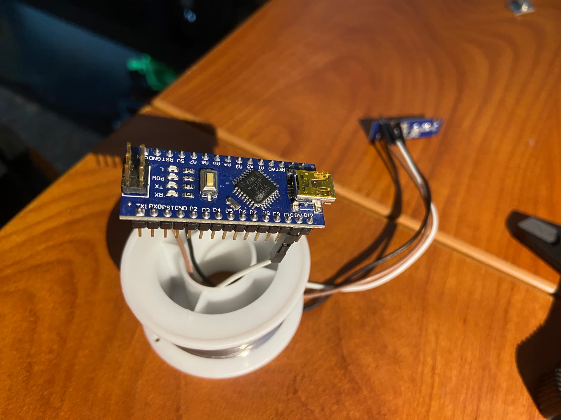
My receiver however is attached with jumpers (the male ends are soldered to the receiver), I also tested these for good connection and they were fine. I don't have a breadboard so this was the best I could do with a camera. Black>5v, Brown>GND, White>D11:
In the picture no, I removed it so it would fit through the roll of solder for a camera stand. I have tested it however with the antenna and still nothing.
I also just swapped it for a different receiver and it didn't change the result.
How do you know the PCB is correct? We can't tell anything from those photos. The PCB adds one more completely unknown quantity to debug.
I strongly recommend to get the setup working on a breadboard, verifying proper connections and functions of all components, before committing to a PCB.
Two comments: 9V batteries are a poor choice for Arduino projects, and those coiled wire antennas are terrible -- even useless when laid alongside a conductive surface, like a PCB ground plane.
Is there a ground plane on your board? If not, your TX antenna will radiate strongly into the Nano. Even if there is, it will. You need to move it away from there. If nothing else, the location will kill the effectiveness of the antenna, as mentioned.
Ditch the coil-ey appendage and replace it with a 7" or so straight wire. Also put the same on the receiver.
Because I can test each circuit for resistance and get a positive result. I also made them with fusion, and can verify that the connections are correct. Here is a screenshot:
I don't actually know, but the tutorial I have found online (linked in post #3)suggests I don't need it.
I have, it was suggested in post #2 and tested in post #7 (still having an issue)
There is not, and I was unaware of that. Can I change the direction of the antenna or am I better off moving the entire component? I will replace the antenna to a 7" wire as well.