My scenario is this:
I have a transmitter circuit using the 433Mhz RF module and a separate receiver circuit. With the two built on breadboards, it works well. Tested distance is over 50 feet (length of my houe) through various walls and doorways. When I built the receiver circuit on a soldered board, no problem. Works well, ie transmitter circuit on the breadboard and receiver circuit on a soldered board.
My next step was to put the transmitter circuit onto a soldered board. I am not getting any response on my receiver circuit (buzzer).
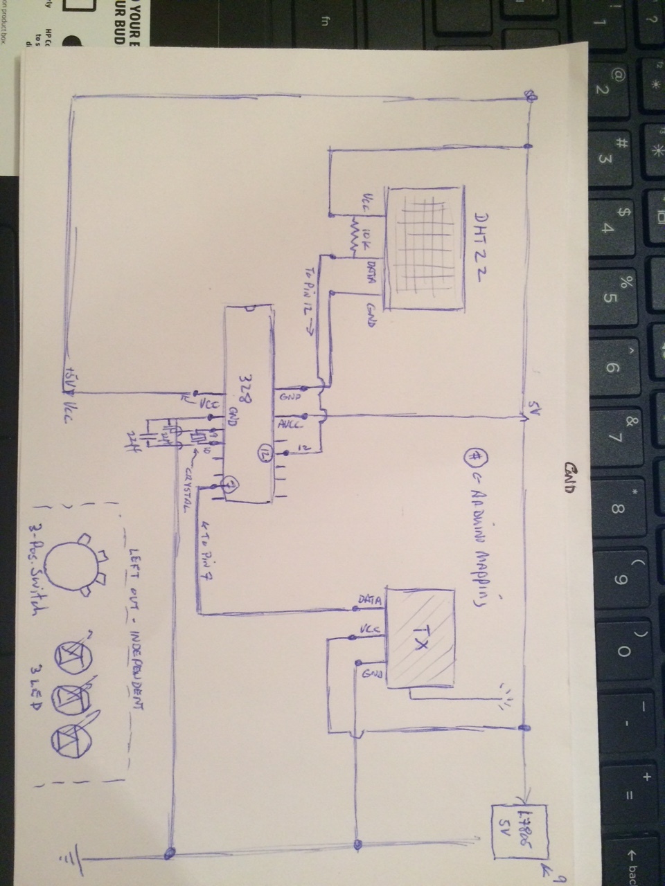
Parts on transmitter board:
1 ATMEGA328 with 16m crystall and required capacitors
1 DHT22 temperature sensor
1 433mhz RF transmitter + antenna
1 5v power regulator (L7805CV)
Program loaded on both breadbaord and soldered board exactly the same file
Trouble shooting:
1 - The first thing I noticed was the ATMega328 chip was installed backwards on the socket. I removed the chip and put it back on the breadboard circuit to check operation. System worked fine on both ends. I put the chip back in the socket on the soldered circuit.
2- The second thing I noticed was that the 16mhz crystal and associated caps were not installed (another unbelievable oversight in my haste to put this together.). I installed the missing parts.
3- I am using the AVCC pin for the 5v supply on the chip (I had read that the more recent chips worked fine with VCC or AVCC powered and it was more convenient to hookup). Just in case, I wired the 5v supply to the VCC also.
4- I checked all connections for continuity and voltage and pin connections. Everything seems in order. The TX data is connected to pin 7 via programming which is located at position 13 on the chip as per the pin mapping for the Atmega328. The measure voltage at the TX module is 4.98v.
5- I added a USB adapter to the circuit via breadboard to check via the serial monitor how the program was behaving. I saw no surprises: the DHT22 temperature was correct and the program made it to the transmit code part of the program:
vw_send((uint8_t *)&c, 1); // Transmit character
vw_wait_tx(); // Wait until transmission is complete..ie, 'The entire message is gone'..See VirtualWire library methods
This is one thing I don't understand: The line of code that tells the program to wait until the entire message is sent: The transmitter must be sending something since the program makes it past this point and goes thru the loop again and again with the right information on the serial monitor. Otherwise, wouldn't the program just sit and wait indefinitely?
If anyone has any suggestions, I would really appreciate the help. The transmission works from the breadboard but not the soldered circuit. On the soldered circuit I put my spare transmitter module without an antenna and it still works fine.
Even though my 328 chip that I installed backwards on the soldered circuit still worked on the breadboard circuit when I tested it, can the problem be a bad pin 13 (pin 7 programatically) on the chip? I really don't want to remove it again unless I have to. I put a new chip on the breadboard for now and I have a couple more spares.
My last option wold be to rebuild the soldered circuit but I don't really want to do that unless I have some basis for knowing what is wrong.
I've attached a photo with the USB connected but not sure what if any help that might be.
Thanks