Hi, @guilhermevi
That is from here;

Have you looked at the code that goes with that video?
Tom.... ![]()
![]()
![]()
![]()
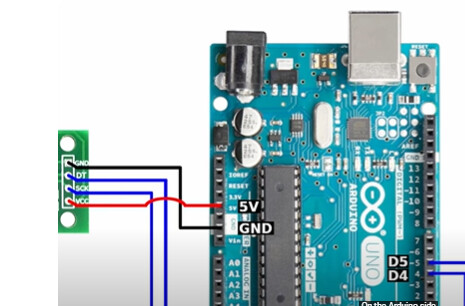
Well that diagram is wrong.
The HX711 Vcc should be connected to one of the 3.3V pins not 5V
Situation is different with 5V arduino board.
Ideally you should use sparkfun HX711 like already suggested.
Or try at 3.3V.
Or use level shifters.
After you fixed the soldering and wired it correctly, try the example sketches that came with the HX711 library. See if you can get a consistent reading, then we can go from there.
I hadn't seen this video yet — I'll try using this code as well. Tnx for the help!
I didn't know that. Do you happen to know what the difference is?
Perfect, then I’ll switch to the 3.3V pin, fix the soldering, and test it again.
In many cases where the sensor can work both on 5V or 3V3 the signal line will obey the VCC voltage. That means: if you feed the board with 5V, the output signal will be 0-5V. If you feed the board with 3V3, the output signal will be 0-3V3.
Some boards are 5V logic (Uno, Classic Nano). Some are 3V3 (Nano 33 family, ESPs).
So,as you're using an ESP, you can either feed the HX711 with 3V3 (and see if it works, considering what Wawa said) or feed it with 5V, but use a logic level converter to bring the signal output to 3V3.
1.7V
@Brazilino explained more detailed above. ![]()
Got it — I’ll try with the 3.3V. But do you know in what situation I would use the 5V in on my ESP32?
I gave you an example --> if you use sensors that work with 5V only (eg almost all HCSR-04). If you don't need the 5V pin on your ESP, just leave it unconnected. There's no harm in doing that.
Mainly if you want to power your board without USB.
Using the example sketches.
Calibration is not the same as tare. Calibration is done once.
You still might need it in this application.
For optimum noise immunity it's always best to drive a bridge circuit with the highest voltage allowable. That will maximize the A+/A- voltage going to the HX711 making it less immune to noise. So after you get everything working, you might find you obtain more stable readings with 5V rather than 3.3V
Looking at your set-up using 5V may well be necessary but let get it working with 3.3V first.
During my lunch break, I went to the store and bought new solder, and I also got some flux to see if it finally works this time!
I also took the opportunity to switch from the 5V in to the 3.3V pin. Now, when I run the test, it's returning "NaN".
Which code are you using?
I used the example code that came with HX711_ADC, the Testing one.
But everything happened so quickly since i had only 5 minutes of lunch time, I didn’t really have time to make sure everything was right before running the test.
Once I get back home, I'll take my time to run the test properly.
Install the HX711 Arduino Library by Bogdan Necula and try the HX711_basic_exmple.ino.
Don't forget to change the pin numbers in the code.