There is no issue with the HX711_ADC library by Olkal. I do not think that @guilhermevi should complicate things by switching libraries mid stream.
2 Likes
If you have that library working on an ESP32-S3 with an HX711 I'm sure that @guilhermevi would love to see your code.
1 Like
Per this thread:
The Sparkfun version of the HX711 breakout board has a separate VCC and VDD pads for separate excitation and logic voltages:
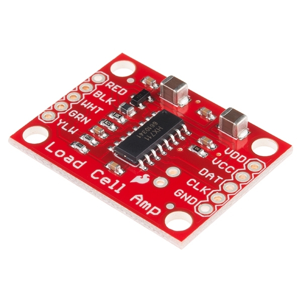
That same thread also points to a hint about modifying a non-Sparkfun 4-pin IO board like yours to use 3.3V and still drive the transistor excitation circuit: Modifying the HX711 Breakout Board for 3.3V operation | Details | Hackaday.io
1 Like
The Olkal HX711_ADC library example Calibration.ino code should work fine (with a Sparkfun VCC/VDD breakout board):

It's AFAIK the only board on the market designed for 3.3volt processors.
It has a 5volt power pin (VCC) for the load cell part of the HX711 and a 3.3volt supply pin for the digital part of the HX711 (VDD).
Common HX711 boards are only optimised for 5volt Arduinos.
Expect instability if you power those with 3.3volt.
Leo..
1 Like
If the hardware was 100% working it might but it is not working. So we need some testing and diagnostic sketches in order to isolate the problem.
Trying to do a calibration on non-functioning hardware doesn't really help to debug. All you will know is that it won't calibrate.
Still need help?
Hey everyone, how’s it going? Sorry for the delay in getting back to you.
The reason for the delay is that we reached a point where we were sure our HX711 wasn’t working properly, so we ordered two new ones, along with two logic level shifters.
@jim-p, I redid the soldering — this time it came out much better. It may not be up to your standards, but for the first time, I was actually proud of my soldering work haha.
Tomorrow we’ll get back to testing, and I’ll bring you some updates. It took a while because the logistics in my country aren’t great, so deliveries usually take more than a week.
Do you have any tips on how to use the logic level shifter to power the HX711 and get the best performance out of it?
@Wawa, Would you mind sharing some tips on how to get the best performance with the components I have?
P.S.: I also bought an Arduino Uno R3, just in case I can’t get it working properly with the logic level shifter.


Hi, @guilhermevi
Solder job on the 711 looks fine.
The level shifter looks okay, but it possibly needed a bit more heat.
Overall, both devices look good.
I hope you are not using lead free solder!!!!!
Tom.... ![]()
![]()
![]()
![]()
Glad to hear that you think the soldering turned out okay! The logic level shifter came with the pins pre-soldered, but if I notice any issues, I’ll try reheating the joints.
I’m using leaded solder, following the great Jim-p’s recommendation!
1 Like
First measure the resistance between E- and GND on opposite sides of that board, before connecting anything. It should be close to zero Ohm. Some of those green boards have a manufacturing defect, where E- is not connected to ground.
Don't use a level shifter board.
Just drop the 5volt-logic data fron the HX711 to 3.3volt with a two-resistor voltage divider: 1k between HX711 data and ESP pin, 2k2 between ESP pin and ESP ground. Don't worry about changing the clock pin, which is an ESP output.
Power the HX711 from 5volt. Anything less than 4.5volt will stop the 4.3volt load cell excitation voltage regulator from working properly.
Test the finished setup:
Measure between E+ and E- with a DMM. It should be very close to 4.3volt.
Measure between A+ and A- with a DMM. It should be less than 20mV.
If not, then your load cell wiring is wrong.
Leo..
I suggest you start with the Uno. Once you have the scale working the way you want then move to the ESP and use the level shifter if required.
I redid the soldering
Looks good. The leaded solder makes it much easier.
Good evening, everyone. I have some updates to share:
- The connection between E- and GND is showing 0.06 ohms.
- Between E+ and E-, we’re getting 4.14V (red probe on E+, black on E-).
- Between A+ and A-, we're reading 6.4 (on the 200m scale, red probe on A+, black on A-).
- At one point, the reading showed -1. We changed the code, and it started giving varied readings. However, when I added weight, the reading decreased; when I removed the weight, it increased. Then it started showing only 0. After a while, it began displaying a number that kept gradually decreasing, and when I added weight, it dropped even more. When I removed the weight, the value increased slightly. I’ve attached an image to show what’s happening.
The setup using the Uno was based on the instructions from this page: https://www.instructables.com/Arduino-Bathroom-Scale-With-50-Kg-Load-Cells-and-H/.
We tested several codes, including:
- Testing (ADC)
- Basic example (HX711)
In the screenshot of the results, the moment it shows values from 2,824,800 to 2,486,880 was when I had placed the weight on the sensor. Before and after that range, there was nothing on it.
On one hand, I’m glad there was at least some reaction when adding and removing weight.
But on the other hand, I’m a bit frustrated, because even using the UNO, I still couldn’t get it to work properly.


Swapping A+ and A- terminals could fix that.
There are no standard load cell wire colours.
Leo..
1 Like
Other that the fact that the readings go down rather than up it seems like it is working.
To get meaningful numbers, you now need to clibrate the scale.
1 Like
What is the size of your weighing platform, it looks gigantic?
How much does the platform weigh?
Is the platform weight evenly distributed on the load cells?
In the first version, the platform was indeed quite large and very rectangular, but we changed that over a week ago. Our new platform measures 50 x 45 cm. I’ll send some pictures of how it looks now.


I really appreciate all the help from you and everyone in the forum. I must admit I’m a bit desperate for this to work, but I still haven’t figured out what might be wrong.

Hi, @marioliv
Please remove the load cells from the 711, and short A+ to A- on the 711 module.
Tell us the reading you get?
Then short B+ to B-.
Tell us what you get.
Tom.... ![]()
![]()
![]()
![]()
You have very long wires and that will make it prone to noise pick-up
Taping the load cell to a platform isn't the best way to make scale if you require any kind of accuracy.
The platform should be made of a very regid material.
You still need to calibrate your scale.
What is the minimum and maximum weight you need to measure?
1 Like
How much weight? 1 gallon of water? 10kg? 20000 grams?
The calibration process subtracts out the zero-weight offset reading (2,824,800 from what you've shown) and divides the difference by the applied weight ((2486880-2824800)/weight=???) to get a counts-per-weight-unit calibration factor. Maybe a calibration factor of (2486880-2824800)/20000gram=-16.868counts/gram is reasonable, and all the calibration process reduces into (reading-offset)*calibrationFactor.
If everything was perfect, that calibration forumla would be enough, but real-world devices include noise. The different libraries can do different averaging schemes to smooth the noise due to construction, gauges, wiring, or operating conditions.