I built a steam-punk-like Zeppelin Lamp with 4 rotors. Each has a 28BYJ-48 Stepper Motor and all wires run together inside.
My goal is to run all 4 motors equally (same direction, same speed, same timing).
Each motor is connected to a driver board. Each board has +-5V and 4 controller pins.
My questions are:
Since the Nano does only have 12 digital pins, does it work when I attach 1 Pin on the Nano with 4 driver boards? (meaning Pin D2 Nano -> 1to4 with one on each driver board, D3, D4, D5 similar).
Is it ok to attach all 4 driver boards 5V+- on the 5V/Gnd on the Nano?
You shouldn't connect 4 motors in parallel to one driver board, but its OK to connect multiple driver boards to shared pins on the controller. For eample, the Protoneer CNC shield can connect two separate drivers (A to ??) to any of the other axes step/dir signals and run them in parallel, or run them on independent pins. The Enable signal is shared by all the drivers.
If you want independent motion, you need separate DIR and STEP pins for each independent motor.
Depending on the driver you use two IO-pins for step / direction can be sufficient
If you need only one direction even 4 IO-pins would be enough.
You can feed in the step-pulses into four drivers that are connected in parallel.
You should describe in more details what components you are using.
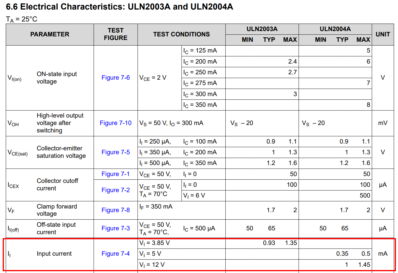
usually the Stepper-motor type 28BY-48 is driven by an ULN2003-chip.
This chip requires 4 IO-pins.
But if you use a A4988 or TMC2209 stepper-motor-driver two IO-pins of the microcontroller are sufficient.
I think @didda means each cable from each stepper is run together inside the Zeppelin, then connected to 4 separate drivers.
If they are the ULN2008 then you can connect each of the four control input pins together to a Nano pin.
So pin 1 of each driver is connected together and then to a pin of the NANO.
And so on with the other 3 pins.
However you will need a separate 5V supply to power the steppers.
I hope that is what you mean.
Can you please post a copy of your circuit, in CAD or a picture of a hand drawn circuit in jpg, png?
Hand drawn and photographed is perfectly acceptable.
Please include ALL hardware, power supplies, component names and pin labels.
A circuit diagram is much quicker and more accurate than words to explain a circuit.
sorry that I didn't do the circuit diagram right away. Here it is.
1 out of 4 works perfectly. I have not tried all 4, since they are already built into the zeppelin and I dont wanna break components.
At the moment, the arduino is powered via USB from my PC for testing. I have a 5V WS2811 LED Stripe inside the zeppelin with a poweradapter - I intend to use this powersource and attach the arduino to it.
How are you powering all this? You don't have any power connections on your diagram. Since you are running all 4 steppers at the same time, you are pulling 4x the amount of current.
as I wrote, my test environment is powered via USB connection of the nano.
For my final setup inside the zeppelin, I have a 5V power adapter which currently runs a ws2811 stripe. I plan to use this source the for arduino/stepper as well.
use the 5V of the arduino nano.
The 5V pin of the arduino nano can not provide enough power
The principle shown here for how to power a RC-servo applies the same way for your stepper-motor-drivers and the Neopixel-strip