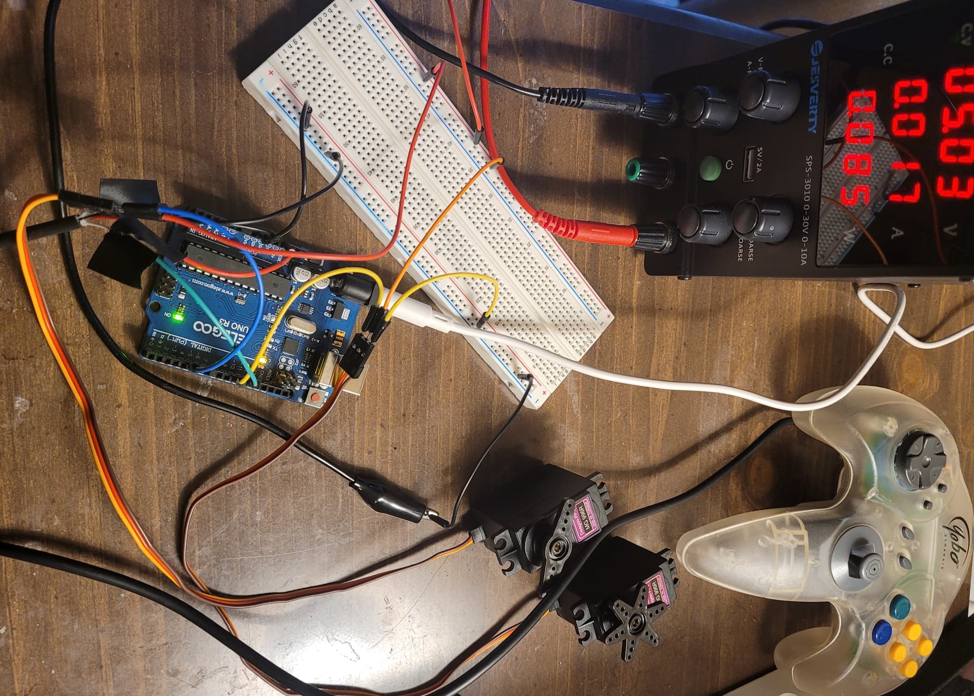
I am working on a robot arm controlled by 6 servo and a stepper. I using a N64 controller to control the arm and the arduino uno is the main board. I am worried the PWM signal is causing twitching of the servos. I have hooked up to pin 5 and 6 and get slight twitch but the go to 9 and 10 and get much worse twitch. I am testing these with a bench power supply so i know its not a powers supply issue could it be the PWM and is there a way to fix this?
//#include <Stepper.h>
#include <Servo.h>
#include <N64Controller.h>

//Name servo motors
Servo s1;
Servo s2;
//Servo s3;
//Servo s4;
//Servo s5;
//Servo s6;

//Variables
//Servo position variables
int pos1 = 0;       // Servo1 position variable
int pos2 = 180;     // Servo2 position variable
//int pos3 = 90;      // Servo3 position variable
//int pos4 = 90;      // Servo4 position variable
//int pos5 = 90;      // Servo5 position variable
//int pos6 = 60;      // Servo6 position variable

// Servo position increment constants
const int pos1_inc = 10; //

// Stepper Motor variables
//const int RPM = 15; // Stepper RPM
//const int stepsPerRevolution = 2048;  // change this to fit the number of steps per revolution

//Arduino Pins
N64Controller Ncon(12);     // N64 Controller pin
const int s1_pin = 5;       // Servo 1 Pin
const int s2_pin = 10;       // Servo 2 Pin
//const int s3_pin = 3;       // Servo 1 Pin
//const int s4_pin = 9;       // Servo 2 Pin
//const int s5_pin = 10;      // Servo 1 Pin
//const int s6_pin = 11;      // Servo 2 Pin
//Stepper myStepper(stepsPerRevolution, 1,7, 2, 8); // Stepper motor pins

void setup() {
  pinMode(12, INPUT);
  Ncon.begin();             // Initialisation
  Serial.begin(9600);       // Start Serial communication
  //myStepper.setSpeed(RPM);  // Set stepper speed
  s1.attach(s1_pin);
  s2.attach(s2_pin,550,2450);
  //s3.attach(s3_pin);
  //s4.attach(s4_pin);
  //s5.attach(s5_pin);
  //s6.attach(s6_pin);
  s1.write(pos1);
  s2.write(pos2);
}

void loop() {
  delay(5);

  //Get a reading from the controller and place it into variables
  Ncon.update();
  //int L = Ncon.L();
  //int R = Ncon.R();
  //int x = Ncon.axis_x();
  //int y = Ncon.axis_y();
  //int D_left = Ncon.D_left();
  //int D_right = Ncon.D_right();
  int D_up = Ncon.D_up();
  int D_down = Ncon.D_down();
  //int C_left = Ncon.C_left();
  //int C_right = Ncon.C_right();
  //int C_up = Ncon.C_up();
  //int C_down = Ncon.C_down();

  //Button Commands
  //if (L == 1 | D_left == 1 | C_left == 1){
    //myStepper.setSpeed(RPM);
    //myStepper.step(30);
  //}
  //else if (R == 1 | D_right == 1 | C_right == 1){
    //myStepper.setSpeed(RPM);
    //myStepper.step(-30);
  //}
  //else{ //rotate > -30 && rotate < 30
   //for (int i = 8; i < 12; i++){
     //digitalWrite(i, LOW);
   //}
  //}

  if (D_up == 1 && pos1 < 180 && pos2 > 0){
    pos1 += 2;
    pos2 -= 2;
    s1.write(pos1);
    s2.write(pos2);
  }

  if (D_down == 1 && pos1 > 0 && pos2 <180){
    pos1 -= 2;
    pos2 += 2;
    s1.write(pos1);
    s2.write(pos2);
  }

  //Serial print data
  Serial.print("D up:");
  Serial.print(D_up);
  Serial.print("\t");
  //Serial.print("X-axis: ");
  //Serial.print(x);
  //Serial.print("\t");
  Serial.print("pos: ");
  Serial.print(pos1);
  Serial.print("\t");
  Serial.print(pos2);
  Serial.print("\t");
  Serial.print("D down: ");
  Serial.print(D_down);
  Serial.println("\t");

//  Ncon.print_N64_status();

}
I did scope it at my work going from pin 5 output to ground and noticed some slight irregularities. When I used pin 9 I noticed the twitch is a lot worse so I am going to scope that pin today.
I apologize, I did not think this was a cross post because that is a programming question asking about best practice and this is a hardware issue. Also, I have had no responses to that post. I would have asked anyone for help if someone had taken an interest.
I am using the Jesverty, SPS-3010 DC power supply, 0-30V, 0-10A. The reason I do not think it is the motor or power supply is because I do not have this issue when I hook up the same motors to an ESP32, but this code is not compatible with the ESP32 so I have to use a different code. I will get a wiring diagram done shortly.
The drawing does not match the code. Why did you define pin names, then never use the names and only used hard-coded numbers? These flaws indicate you have caused mistakes in the code and the connections.
Your project will only work if you clean up... so start by removing every device and wire.
Measure the output voltage of the power supply. If the voltage is within tolerance for the Arduino, connect the power supply to the Arduino (and ground).
If your n64 controller truly has a data wire, and the data wire is connected to Arduino pin 12 (and power and ground), I assume pinMode() is set to INPUT. Make a sketch that reads the n64 and prints the output to Serial Monitor. Make the controller do all the movements and take notes on the movements and the serial monitor output.
Post a drawing of these two steps, your code, the output, and your observations here.
I measured the voltage of the power supply and it measures 5.0 V on the multimeter. I have tried powering the Arduino Uno from the power supply with the servo motor and powering them separately as shown in the first schematic. The first schematic shows my trails with only one servo and the twitch is still present.
I have all the extra code in there because it is intended to be for all 6 servo and 1 stepper when complete. I have gotten rid of all the "extra" code and Libraries so it is only the first two servos.
The twitch is under no load and it twitches when not moving and when moving. I worry it is the board that is causing the issue. The only other thing I can think of checking if the Servo.h library code is causing this. I have hooked it up to oscilloscope and there are some irregularities.
Is there another library that can create the PWM on Arduino Uno?
I have purchased PCA9685 servo driver see if this helps it does run a different library.
Remove the "delay(5);" from your sketch. Eliminate the use of "delay" in all your code.
Is there a reason to attach your servos differently?
  s1.attach(s1_pin);
  s2.attach(s2_pin,550,2450);
Monitor the power supply as the servo motors move. The servos' low limit is 4.8vdc.
Use just one servo for testing... then add a second servo.
Servo motors are under power and command when "not moving" so I would expect "moving" and "not moving" to behave similarly.
What do you see in the Serial Monitor?
Libraries can interfere if your sketch is not written for the library. A library could be "blocking" other commands...
I put together this "no library" servo program that uses pulse width to position the servos. You could try it with your hardware. Understand that the simulation pulse width will be different from your servos, so you will probably need to adjust the pulse width in the code to suit your servos for the full 180 degrees.
I have used your code to create the PWM signal and the twitch has gone away. I altered it to increase and decrease pulse width based on serial input. I am looking into this further and maybe an old version of the servo library will not give me this issue, but it did start twitching again when I used the code with the potentiometer. This could be because I powered both off board. I will try again with my power supply and see if twitch goes away.
Here is my version of code with serial input, also, getting rid of the delay(5) did help reduce the twitch.
unsigned long offTime, totalTime = 20000; // PWM time a 20ms pulse cycle
unsigned long onTime = 1525;
int test;
bool onTimeFlag, offTimeFlag; // indicate xTime has finished
unsigned long currentMicros, previousMicros = 0; // timers
const byte servoPin1 = 9; // servo pin
const byte servoPin2 = 10;

const int posInc = 250;
int oldTime; // for debug
int mapTime; // for timing

void setup() {
  Serial.begin(9600); // for debug
  pinMode(servoPin1, OUTPUT); // prepare the servo data pin
  pinMode(servoPin2, OUTPUT);
  digitalWrite(servoPin1, HIGH); // begin "ON" pulse
  digitalWrite(servoPin2, HIGH);
}

void loop() {
  //potentiometer = analogRead(POTENTIOMETER); // read the potentiometer
  if (Serial.available() > 0) {
    // read the incoming byte:
    test = Serial.read();

    switch (test) {
      case '1':
        if(onTime > 525){
          onTime = onTime - posInc;
        }
      break;
      case '2':
        if(onTime < 2525){
          onTime = onTime + posInc;
        }
      break;
    }
    // say what you got:
    Serial.print("I received: ");
    Serial.print(test,DEC);
    Serial.print("\t");
    Serial.print("PW:");
    Serial.println(onTime);

   }


  offTime = totalTime - onTime; // calculate offTime LOW signal

  currentMicros = micros(); // start a new pulse train timer

  // EVENT 1 - PWM OFF - occurs at 1m to 2ms (1000us to 2000us) after start to end the HIGH pulse
  if (currentMicros - previousMicros >= onTime) { // bypass this for condition 1000us to 2000us
    if (onTimeFlag == 0) { // test if onTime has previously been tested
      digitalWrite(servoPin1, LOW); // set pulse OFF for offTime
      digitalWrite(servoPin2, LOW);
      onTimeFlag = 1; // onTime is finished, do not enter this condition until end of offTime
      // previousMicros = currentMicros; // previousMicros is new "zero" for offTime
    }
  }

  // EVENT 2 - PWM ON - occurs every 20ms (20000us) to start a new pulse
  if (currentMicros - previousMicros >= offTime) { // bypass this for condition 18000us to 19000us
    onTimeFlag = 0; // offTime is finished at 20ms. Reset onTimeFlag
    digitalWrite(servoPin1, HIGH); // set pulse ON to begin onTime
    digitalWrite(servoPin2, HIGH); // set pulse ON to begin onTime
    previousMicros = currentMicros; // previousMicros is new reference time "zero"
  }
}
Very good. Definitely use an external power supply for the devices. Fast movement of the potentiometer might create large steps which might make the motor change roughly. Read about ROTARY ENCODERS (to replace a potentiometer) which give single pulses as you turn the knob, each pulse can be translated to one motor step, rather than a resistance of a potentiometer that might change resistance over time, or lose smoothness.