Thanks for your help,
I hope this is the right place to post this.
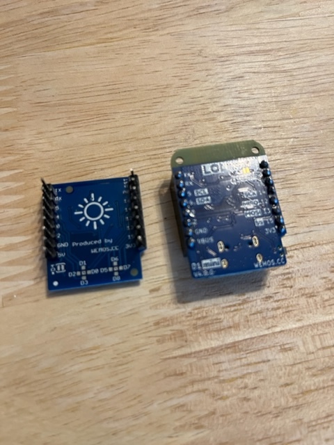
I am trying to find a good way to attach an external button to my WEMOS D1 mini (V4) with RGB LED Shield. I do not want to increase the height of the module, I want to place the button externally.
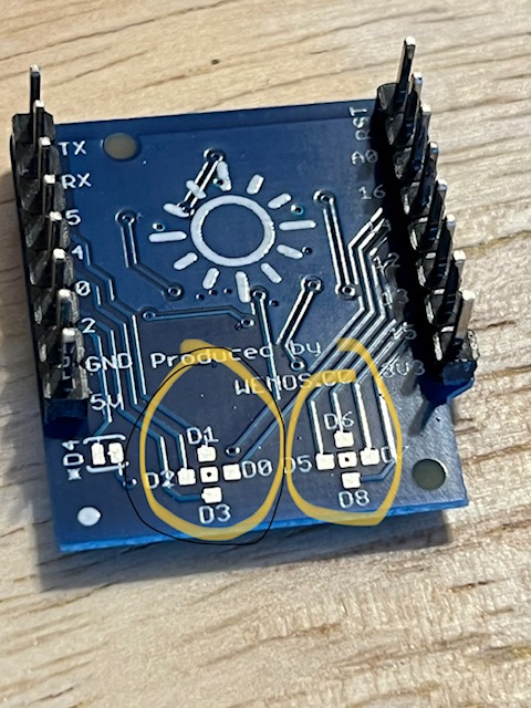
I'm not sure how best to attach a wire long term. I tried soldering to pins once (worked until it broke off) and tried soldering to a tall header (didn't work, not a reasonable long term solution).
Any ideas? I have attached photos.
Gentle tips on soldering are appreciated but please be nice, I am just learning and have tremors so my joints are not pro-level yet
I have male pins, short headers and tall headers.
I have a program written now that mostly does what I want and has 2 buttons. I can actually trigger the buttons by just touching the pin on the board. I'm not sure why that is and if that is a good or bad thing? The wire on the long pin didn't work (maybe a bad solder joint?) 99% of the time. Occasionally I was able to touch the end of the wire (and no ground) and trigger the button. Again, I'm not sure if that's a good thing or a bad thing?
do you mean to the pin where it pokes out the top and make sure it also touches the board? Or do you mean the tiny little squares on the back of the shield that are arranged in crosses?
If your buttons are responding to noise that is generally a bad thing. You might want to look up standard approach to buttons on the forum. In general a pin is pulled high with a resistor and gets grounded through the button. The uC reads the LOW as a button press. You often need some debounce code to avoid the button turning off and on multiple times when pressed due to slight jumping of the contacts.
thanks. I'll look it up. I'm using a 3.3v board (WEMOS D1 mini v4). In another sketch I wrote I had no problem, but with this sketch I seem to be running into problems. I'm using the same hardware and I can't figure out the difference in the sketches. Thanks for your advice. I'll do some more reading in the forums and see if I can figure out what element is different between the two sketches.
Thanks. I'm not a professional, but I'm fairly certain my set up is S3 with 3.3v. It's something in the sketch that's not working. They both use INPUT_PULLUP but one is all done at once checking, and the other is done across a state machine cases. On the second one it seems to get stuck on LOW and does not register that it goes back up to HIGH after I release the button and therefore does not advance to the next case.