Hi together, this is my first post in this forum, so please be merciful with me if I break any rules.
This discussion is kind of what i am struggeling with. I have an ATtiny414 (also an ATtiny1614) and i managed to program it with jtag2updi from Arduino IDE 1.8.13 using megaTinyCore and also from ATMEL Studio 7 following this guide. Blink Sketch and some easy ISRs on Button Change worked like a charm and i was very happy how easy and intuitive everything was.
But than i tried to print something to a console and gets kind of frustrated. I uploaded a sketch
void setup() {
Serial.begin(9600);
}
void loop() {
Serial.print("Hello from ATtiny!");
}
to the ATTiny 1614 (that worked without problems as well as blink sketches, etc.) and connected the PB2 pin of the ATtiny with the RX pin of a second arduino (and both GND) and assumed that i am able to see incoming messages at the serial monitor of the second Arduino.
The RX LED of the Arduino starts blinking but i was disappointed to see that nothing was shown in the Seriel Monitor. I also tried with hterm. I checked if the TX port of the ATtiny worked in general and if the Serial Monitor will show something if i sent messages from an addtional Arduino. I also checked all other Ports of the ATtiny, because there seems to be some confusion about the default and alternative UART ports.
- I saw some discussion about the BAUD rate if using Prescaler. Are there any adjustments needed to get the arduino implementation working properly?
- If the RX LED of the receiving Arduino is blinking, i would assume that this indicates that the ATtiny is sending some bits. How to validate that (without an osciloscope)? hTerm shows nothing as well

- Any additional tips&hints how to get U(S)ART working for ATtiny Series 1 µCs are highly welcome! For Arduino IDE as well as for ATMEL Studio...
Now that should be the TX pin of your second arduino.
Because that TX pin is connected to the RX pin of the USB<>Serial adapter of your arduino.
(and make sure that nothing is running on that second Arduino, so that it's TX pin is in input mode).
Thank you very much for your answer!
I dont get why it should be TX.
Attiny PB2 (TX) ↔ Arduino Pin 0 (RX/Serial Monitor) should be fine, shouldn't it ?
Sending from Attiny and receiving by Arduino.
- Is a baud rate of 9600 suitable for the attiny @ 3.33MHz (20MHz with prescaler 6)?
- Do i have to disconnect the connection of the UPDI programmer after flashing ?
- According to the datasheet, PB2 (TX) and PB3 (RX) are used for serial communication. Can anybody confirm that ?
Thanks in advance.
Attiny PB2 (TX) ↔ Arduino Pin 0 (RX/Serial Monitor)
Is fine if you want to process the received data from your Attiny on your Arduino.
I assumed you wanted to intercept the serial output of your Attiny to your PC, by using the USB<>Serial adapter that is part of your Arduino.
What arduino are you using?
What device are you using to program your attiny?
I now understand you have a program running on your Arduino that reads the serial data coming from your Attiny?? I suggest you post that sketch here.
9600 can easily be done with 3.3MHz.
UPDI can be left connected.
PB2 (TX) and PB3 (RX) is correct for the attiny414
Yes, that is correct. I assumed that i can just use the Arduino as a USB ↔serial converter. And now i got it working. I missunderstood your first reply:
and that was actually the solution.
Just to get sure that i understand it properly and prevent somebody from doing the same thing:
The Pin Descriptions are from the perspective of the µC not from the Serial-to-USB adapter, what makes sense to me. Accordingly i have to connect the TX of the ATTiny to the
TX (!) of the Arduino (which is the RX of the USB-to-Serial adapter) to see the data sent from the ATtiny. Correct?
Thank you a lot for your help!
Correct. That's what I mentioned in post #2.
But why not buy a few CH340 USB<>Serial adapters. They are cheaper than an Arduino and with a diode between TX and RX on the adapter, you have the fastest UPDI programmer to have.
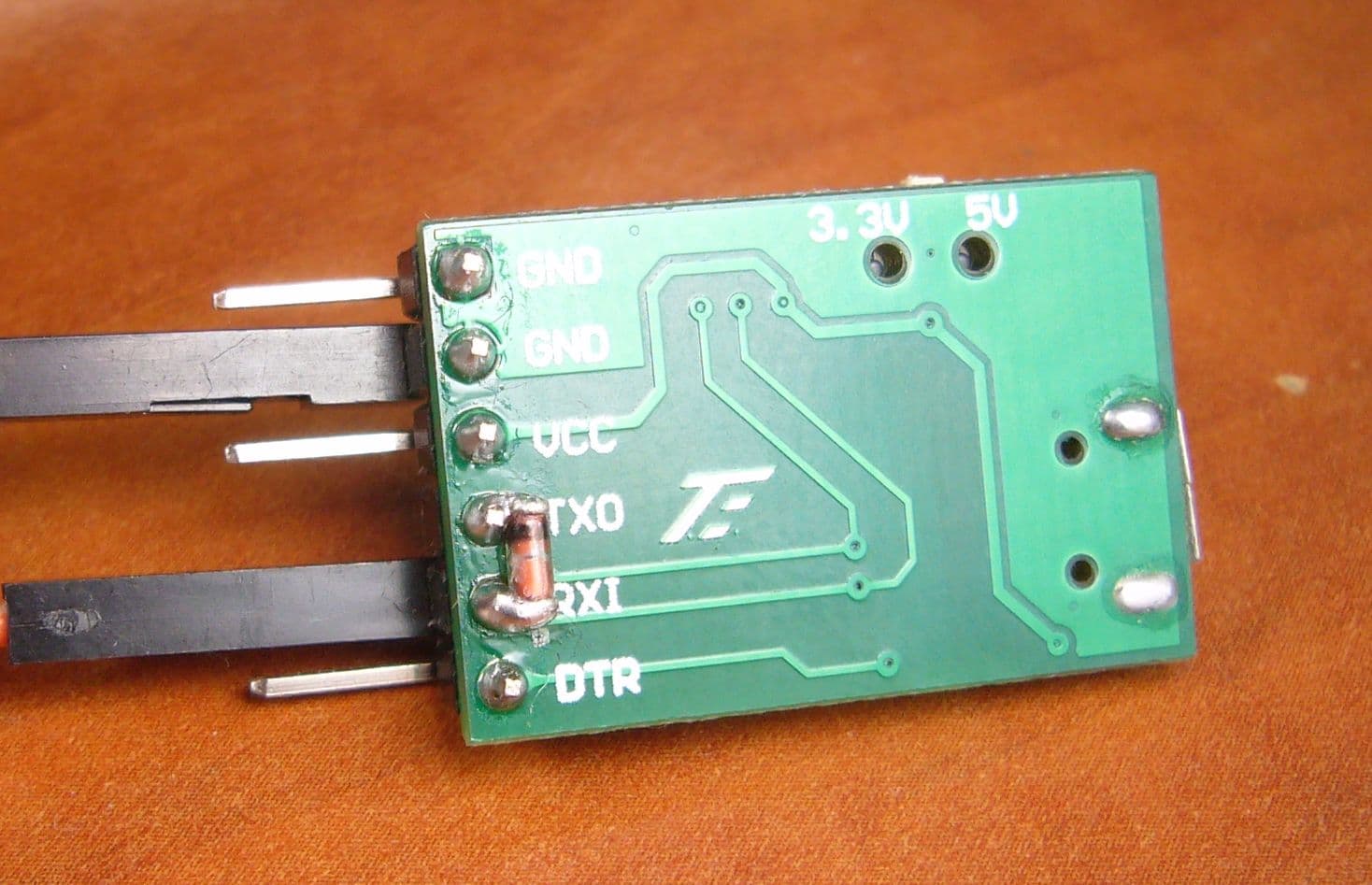
I am using this one and on the back I added a diode and cut off the TX pin.
There's really no reason to, except that I have to wait for it because my only CH340 is broken.
And i was curious how to do it with Arduinos only.
Seems to be a nice solution. I will try that if i received one. (btw the link seems to be broken)
Thank you a lot for your help. I marked this topic as solved.
No, unfortunatly not. The Link itself works but on the AliExpress Site there is a message shown "Sorry, the page you requested can not be found:(". Maybe you can just post the name of the Adapter? But i think all of the CH340 USB-Serial adapters will work, right?
The forum is doing something with my link it seems when it want's to show a preview, so I try it in code tags now and the forum does not touch it
https://www.aliexpress.com/item/1005004824134193.html
For the CH340, they will work, but one works more stable and faster than the other, depending on the presence of RX/TX leds and any resistors used in series on the adapter.
As you can see I tried all sorts of them, but the little green one in the picture turned out to be the one that works best at Turbo upload speed and only required a single diode to do so. Funny enough it was the cheapest one I ever found.