Hello Arduino form,
Doing some tests to understand the relation between the
Internal Clock speed used to compile s sketch and the output
of the ATtiny85. Tests results copied herewith below.
The first three tests indicate that there is a directly proportional
relation between the internal clock speed and delay output from
the microprocessor. That is, the 8 MHZ clock speed sets the
delay output at one second when the delay is set on the sketch
at 1000 ms.
And if the sketch is compiled at 16 MHZ the
delay output doubles to two seconds. And conversely,
if the click speed is set at 1 MHZ the LED blinks
at .25 hertz.
The thing which is doesn't seem to make sense is
when, in the fourth test the delay is set to
2000 ms. The expected outcome was the oscillation
would go to two seconds. But the result was
the LED stays on for eight seconds and stays
off for eight seconds. This is with the sketch
compiled at 8 MHZ.
What am I missing?
Thanks.
Allen Pitts
ATtiny_Blink_230809.ino (655 Bytes)
/*
  Blink  230809
  Turns on an LED on for one second, then off for one second, repeatedly.

    modified 8 May 2014
  by Scott Fitzgerald
 */
//int LED = PB4;

// the setup function runs once when you press reset or power the board
void setup() {
  // initialize digital pin 13 as an output.
  pinMode(4, OUTPUT);
}

// the loop function runs over and over again forever
void loop() {


  digitalWrite(4, HIGH);  // turn the LED on (HIGH is the voltage level)
  delay(2000);            // wait for a second
  digitalWrite(4, LOW);   // turn the LED off by making the voltage LOW
  delay(2000);            // wait for a second
}
Test 240822.1 Internal clock 8 MHZ
Preconditions
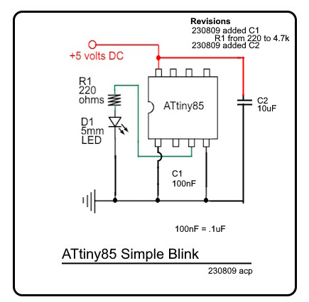
- Schematic: ATtiny85 Simple Blink, attached
- Sketch: ATtiny_Blink_230809.ino (delay=1000)
- Internal clock: 8 MHZ
Expected result : D1 oscillates on and off at 1 hertz
Actual result : D1 oscillates on and off at 1 hertz
Test 240822.2 Internal clock 16 MHZ
Preconditions
- Schematic: ATtiny85 Simple Blink, attached
- Sketch: ATtiny_Blink_230809.ino (delay=1000)
- Internal clock: 16 MHZ
Expected result : D1 oscillates on and off at 2 hertz
Actual result : D1 oscillates on and off at 2 hertz
Test 240822.3 Internal clock 1 MHZ
Preconditions
- Schematic: ATtiny85 Simple Blink, attached
- Sketch: ATtiny_Blink_230809.ino (delay=1000)
- Internal clock: 1 MHZ
Expected result : D1 oscillates on and off at .25 hertz
Actual result : D1 oscillates on and off at .25 hertz
Test 240822.4 Internal clock 8 MHZ
Preconditions
- Schematic: ATtiny85 Simple Blink, attached
- Sketch: ATtiny_Blink_230809.ino (delay=2000)
- Internal clock: 8 MHZ
Expected result : D1 oscillates on and off at 2 hertz
Actual result : D1 oscillates on and off at 8 hertz


