Stepper motor without torque, voltage drop or DIR short issue? Arduino UNO + CNC shield + DRV8825 + nema17 stepper motors

tl;dr VMOT is 3.8V on the DRV8825, and I've read that it needs 8.2V (minimum 7.8V), but my power supply is delivering 12V at the input terminals. Not sure if this is board or driver issue or if I need a 24V power supply. I also measured continuity between CNC shield and driver DIR pin, which I understand should not be the case (measure's 12V when powered, but should be 5V for logic). Faulty CNC shield or insufficient power supply?

Problem: stepper motors don’t move, more specifically they don’t seem to be energized because they have no holding torque.

Project: building a CNC plotter as described here: https://howtomechatronics.com/projects/diy-pen-plotter-with-automatic-tool-changer-cnc-drawing-machine/

Parts:

Arduino UNO
V3 CNC shield
NEMA stepper motors (1.5A)
DRV8825 drivers tuned to 0.6V, as in 0.8 * 1.5 / 2 (80% of 1.5A/2 for motors)
12V 15A power supply (inline 10A fuse between supply and board)

Wiring setup:

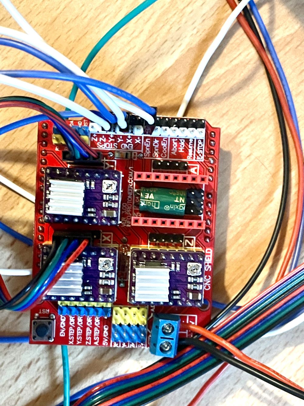
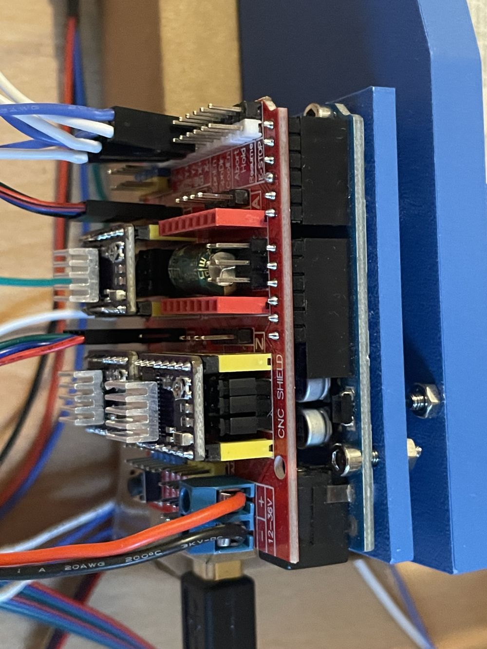
Exactly as in the link above but here are my photos (removed one of the motor connections for clarity):

Troubleshooting:

The good news is the firmware/software is loaded and communicating properly with GRBL software (Universal G-Code Sender and GRBL Plotter), and the limit switches are communicating correctly.

I understand this is not a CNC/GRBL forum so I’ll spare the details unless asked, but the one relevant point is I tried various parameter settings for the motors with no luck, including reversing the enable pin ($1=255, $4=0 or 1)

I checked voltages and they are as follows:

CNC board:

Power input terminals = 12 V
5V to GND = 4.7V

driver pins:

VMOT = 3.8 V
A1/A2 = 4.3 V
B1/B2 = 0 V
FAULT = 4.6 V
ENABLE = -0.1 V
RESET = 4.2 V
SLEEP = 4.2 V
STEP = -0.1 V
DIR = 12 V

VMOT to shield power input +ve = 12 V

Is the DIR @ 12V a problem? I thought that should be 5 V as it’s logic. I tested continuity (while OFF) between +ve CNC board terminal and driver DIR pin and get continuity (with and without Arduino connected).

B1/B2 being 0V was weird, but I'm getting a 2.5ohm resistance on the motor pins.

My first thought was that I actually need a 24V supply but before I take the brute force method I want to ask if there is a potential issue with the boards or wiring that is causing a potential voltage drop? I’ve read that 12V should actually be enough.

My second thought was to replace the CNC shield and maybe drivers and try again (and maybe also try the A4988 drivers but from what I read that shouldn’t be better). I had a fourth driver as a spare, but it gave the same readings.

I hope I covered everything. I couldn’t find any other posting with exactly this issue but did learn a lot about other sources of failure.

Please make and post real schematics. The word description is confusing.
Please post the code.

GRBL firmware contain 18 files
@danduino42 howtomechatronics.com is web page of some enthusiast like you or me. so it is not really reliable.
check connection to the stepper, may be you(or manufacturer) swapped 2 wires of different coils. one coil you can determine by shorting two wires, if motor stall - wires of one single coil are founded, other two wires - another coil. if all 4 wires are short circuited, the stalling is not so hard and with force you are able to rotate the shaft.

I tried the code below, but also the code in this link:

#include <AccelStepper.h>

#define X_STEP_PIN 2
#define X_DIR_PIN 5
#define Y_STEP_PIN 3  
#define Y_DIR_PIN 6
#define Z_STEP_PIN 4
#define Z_DIR_PIN 7
#define ENABLE_PIN 8

AccelStepper stepperX(AccelStepper::DRIVER, X_STEP_PIN, X_DIR_PIN);
AccelStepper stepperY(AccelStepper::DRIVER, Y_STEP_PIN, Y_DIR_PIN);
AccelStepper stepperZ(AccelStepper::DRIVER, Z_STEP_PIN, Z_DIR_PIN);

void setup() {
  pinMode(ENABLE_PIN, OUTPUT);
  digitalWrite(ENABLE_PIN, LOW); // Enable drivers
  
  stepperX.setMaxSpeed(1000);
  stepperX.setAcceleration(500);
  stepperY.setMaxSpeed(1000);
  stepperY.setAcceleration(500);
  stepperZ.setMaxSpeed(1000);
  stepperZ.setAcceleration(500);
}

void loop() {
  // Move X axis
  stepperX.moveTo(200);
  while(stepperX.distanceToGo() != 0) {
    stepperX.run();
  }
  
  delay(1000);
  
  // Move back to start position
  stepperX.moveTo(0);
  while(stepperX.distanceToGo() != 0) {
    stepperX.run();
  }
  
  delay(1000);
}

I get no compile errors and it is uploaded but I get no reaction.

The DRV8825 boards are all plugged in upside down. Presumably they are all fried.

1 Like

Thanks for the suggestion. I was thinking of doing this but wasn't sure if I was going to damage anything. Which wires exactly should I short?

The unusual thing is that there are three motors and three drivers, all displaying the same "issues". So it's unlikely the hardware except I was thinking may the CNC shield. But I can try as you suggest if you give me a pointer on what you mean exactly?

Aw man, I thought I triple checked that... Okay that would explain the weird voltages... Luckily they are pretty cheap. I'll buy some new ones. I should have thought of that before I tested the fourth one...

Do you think I may have damaged anything else in the process? That I could test also.

Aw.

Okay the upside down drivers make complete sense. If it's rotated 180 degrees then you get the correct 12V between the VMOT and GND and DIR is at then correct voltage too...

I think this may be the solution... embarrassingly... I'll order new drivers and report back.

Hopefully I didn't damage anything else?

extremely usual

as i said about swapping by manufacturer.

if you have not better idea take any wire, the bipolar stepper motor have only 4.
take motor in your hands, rotate shaft, feel resistance, take any 2 wires, connect them together, rotate shaft, feel resistance, if same resistance - disconnect one wire and exchange with one of left two.

1 Like

UPDATE: after replacing the drivers indeed everything now works. And also the shield because the fuse was blown on that as well.

For posterity: I noticed that on the arduino shield and on the underside of the driver there are labels for the enable pin ("EN") and that made sure I could line it up properly.

Thanks for the helpful suggestions! I learned a lot on the way.

This topic was automatically closed 180 days after the last reply. New replies are no longer allowed.