Doing that would be very very dangerous to bring internal 1.1 V in conflict with AVCC/VCC and damaging the ADC in case register values are not set correctly.
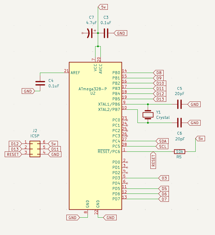
Don't connect AREF-pin with AVCC/VCC; rather connect a 0.1 uF capa between AREF-pin and GND.
If the code is well written, this shouldn't be a problem. But I get what you are saying. I can tell you that I've never had a problem running code developed on a 16MHz Nano on a standalone ATMEGA328 @8MHz.
It's true that it can, rarely, be a problem for some particular baud rates when using UART communications because the transmitter and receiver's clocks may not match closely enough.
But no such problem exists for i2c because there is a separate clock signal produced by the master device. The slave devices clocks are irrelavent, they follow the master's clock.
I agree, Paul, "if the code is well-written". But, being honest, I'm prone to mistakes and have limited experience so I'm trying to reduce some variables. Obviously, I'm not avoiding all variables or I wouldn't be breaking this chip out as a standalone.
You are correct, of course, about the I2C clocking. Good point, I should have been thinking.
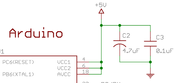
The 4.7uF is from the Arduino schematic in ArduinoNano30Schematic.pdf, see attached.
I'm using global labels because the screenshots I'm attaching are page 2 of a schematic. I just found "labels" yesterday, this is the first time I've used them.
Like I said do not rely on those schematics to be correct. There will be several factors that will determine whether you need additional bulk bypass and how much you need including how you layout the PCB.
The more time you spend up front doing it right, the less time and money you will spend doing re-dos later on.
I understand about the bypass caps. I don't know enough to calculate that so I'm going by the resources I have at-hand and asking here.
Yes, very much agreed about doing it right in the planning phase, again, that's why I'm here. I'll spend days or weeks, whatever it takes, in the planning to avoid failures and re-dos. Then I'll have boards made, realize I still made a mistake, and do it again anyway. The universal failure is not trying.
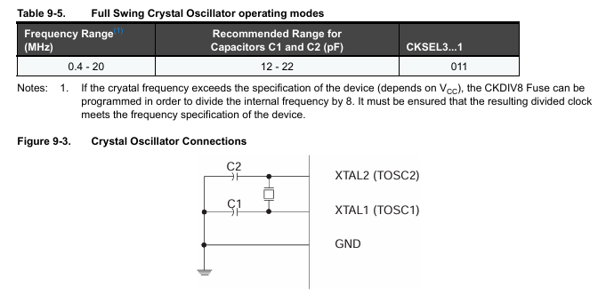
Here's the section from the datasheet for the ATMega328 regarding capacitors for the crystal:
The datasheet makes no reference that I've seen to considerations of stray capacitance in regards to the crystal capacitors. If that's a foregone conclusion for "those who know", I don't know.
Thank you, Paul. Good point about the I/O pins. I'm not (yet) limited by the pins on the "factory" Arduino Uno or Nano but it's still a good point. Reducing components and footprint space isn't a bad thing, either.
I spent about 3 minutes reading that link. Soon, I have to leave for a day or two, I'm running out of time in front of the computer. I'll have to devote more time to the subject when I return. In the meantime what I got from that little reading is that this "MiniCore" requires a different bootloader, UrBoot. Further reading tells of support for printf() which sounds like MiniCore is a replacement for the compiler for the ATMega328. Maybe that's poorly-worded: maybe not a "replacement" for the compiler but a replacement for whatever it is we call the layer between the compiler (translator) and the produced machine code. Support for printf() is a thing as I found in my first topic I posted in this forum.
What's the "executive summary" of what MiniCore is? That would help me to get a frame of reference in my head. Of course, I'm going to go search for that online, but asking you here still seems beneficial and wise.
To find the capacitance of CL1 and CL2 (labeled as C1 and C2 in your image) you could use the following equation:
CL = (CL1 × CL2)/(CL1 + CL2) + Cs
Where:
CL: is the load capacitance. It is the terminal capacitance of the circuit connected to the crystal oscillator. This value is specified by the crystal manufacturer.
CL1 and CL2: are the two external load capacitances.
Cs: is the stray capacitance. It is the equivalent parallel capacitance seen by the crystal.
The main goal is to determine the values of CL1 and CL2. We can rearrange the above equation as follows:
CL - Cs = (CL1 × CL2)/(CL1 + CL2)
Assuming symmetric values, i.e., CL1 = CL2 = C:
CL - Cs = C/2
C= 2(CL - Cs)
Assuming you are using the LFXTAL023401 part number, we can find these two values:
What's the "executive summary" of what MiniCore is?
Minicore supports chips "similar" to those in the Standard Arduino lineup (ATmega8, ATmega168, ATmega328P), but supports more chips (ATmega48x, ATmega88x, ATmega328, ATmega328PB), with more options (various internal and external clocks, with or without -lto, different baud rates, and more!)
Minicore has "always" used a newer version of Optiboot that has the ability for the user code to write to Flash, but recently switched to urboot
urboot is smaller, supports EEPROM, writes flash, does autobaud, and has some other useful features.
Okay, I was away but spent some time reading and watched a video on the subject. My condensed takeaways are: MiniCore allows the use of more of the family of ATMega328 uC (and others), adds printf(), and opens up a host of clock options. The ATMega328PB was explicitly mentioned in the video I watched. As I've only used the Nano clones, and being new to the Arduino "universe", I've not encountered these limitations. That is not to say that I'm not interested in or will not be using MiniCore. In my current project, eliminating the crystal and caps would be beneficial. Plus just general learning.
I take, from your comments, that the Arduino IDE limits capabilities such as using the on-board 8Mhz clock or running on 3.3v. I'll ask a dumb question: how does the Arduino IDE limit the voltage? Chip selection, register settings, something else?