Hi,
You mention "shunt capacitance", I assume that's synonymous with "stray capacitance"; is that correct?
In theory, the stray capacitance is the parasitic capacitance present on the PCB plus the capacitance of the oscillator pins OSC_IN and OSC_OUT. However, almost all IC manufacturers do not specify the oscillator input and output capacitance.
On the other hand, the shunt capacitance is the capacitance of the metallic plates in the cristal, see picture below (The shunt capacitance is a parameter given by the manufacturer)

As you can see, they are two different parameters, however, I took the liberty of interpreting Cstray as Cshunt.
Next, you use the value of 7pF; is that a "rule-of-thumb" for stray/shunt capacitance?
In this case, manufacturers will always give you the CL (C_Load) and C0 (C_shunt) values. If you check the LFXTAL023401 datasheet for example, you will be able to see these two values

If we check another crystal, the 830108313809 for example, we can see these two values

If I were to select that crystal, the calculations would be, again, took the liberty of interpreting Cstray as Cshunt:
CL = 12pF
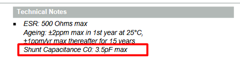
Cstray = 3.5 pF
C = 2(CL - Cstray) = 2(12pF - 3.5pF) = 17pF (Select the closest standard value)
Finally, as you said, a "rule of thumb" is to select a Cstray on the order of 2~5pF. Always check the data sheet of the crystal you are going to select.