Battery Voltage Measurement with OP Amp

raschemmel:
There's no current control. That's a simple comparator. What is the cylinder under the comparator ? Is that a battery ?

That is a resistor. It's drawn the same as his other resistors.

The current through the battery forms a voltage through that resistor. The voltage is then fed back into that op amp.

Its an op amp because its drawn the same as his other op amp. Also, in this application, it can not just turn the FET on and off. It needs to operate in its linear region to form just the right resistance necessary for the desired current to flow.

If that's a current limiting resistor, then the value should be chosen to drop the difference after subtracting 1.4V +1.4V + VDSFET .

If we assume:

VDSFET = 1.0 V,

Battery 1 = 1.4 V (charged)
Battery 2 = 1.4 V (charged)
Then the battery needs to drop 12V -1.4V-1.4V-1.00V = 8.2V

If we assume a Charging current = 300 mA ,

Then RCL = 12.0v/0.300 A = 27.3 ohms
PR = 0.300A * 8.2V = 2.46 W (round up to 3W)

RCL = 27 ohm/3W

he current through the battery forms a voltage through that resistor. The voltage is then fed back into that op amp.

Yes, thats not feedback though, the comparator operates in open loop mode.
Thats the input voltage and the Vref for the comparator is the +V pin.

If +V > -V, Vout = +Vcc
+V < -V, Vout = 0V

Vref = 8.2 V (in above example)

The "feedback " line , as you call it is connected to the wrong pin on the comparator.
The operation should be :
( 0.30 A * 27 ohms = 8.2 V)

If Icharging < 0.3A +V < 8.2V
If Icharging > 0.3A +V > 8.2V

If Icharging < 0.300 A (-V < 8.2 V)
Vout = +Vcc (fet ON)

If Icharging > 0.300 A (-V > 8.2 V)
Vout = 0 V (fet OFF)

raschemmel:
Yes, thats not feedback though, the comparator operates in open loop mode.
Thats the input voltage and the Vref for the comparator is the +V pin.

If +V > -V, Vout = +Vcc
+V < -V, Vout = 0V

Vref = 8.2 V (in above example)

The "feedback " line , as you call it is connected to the wrong pin on the comparator.
The operation should be :

If Icharging < 0.300 A
Vout = +Vcc (fet ON)

If Icharging > 0.300 A,
Vout = 0 V (fet OFF)

That is not a current limiting resistor. It is a shunt to get a current signal. The current in the resistor has the same direction whether charging or discharging due to S1-S3 changing state. The current is limited by the FET operated in its linear region.

Honestly, if you don't know this stuff then it might blow your mind to discover this is the same principle behind how an LDO works. Check out Fig. 2 -> Understanding LDO dropout.pdf

It's a very common circuit, actually. I have one in my hand right now that uses an ATmega32U's DAC to control the positive input to the op-amp so that the current level is variable. I verified its operation from 1uA to 2A with an 8.5 digit HP3458A.

That is not a current limiting resistor. It is a shunt to get a current signal

Ok. I thought you said it was a resistor.

It's a very common circuit, actually. I have one in my hand right now that uses an ATmega32U's DAC to control the positive input to the op-amp so that the current level is variable. I verified its operation from 1uA to 2A with an 8.5 digit HP3458A.

Thanks for the link. Do you have a schematic for the one you have ?

raschemmel:
Ok. I thought you said it was a resistor.

A shunt is a resistor. It's just a resistor intended to convert a current into a voltage signal.

Can you post the Reply# of the post where the OP describes the current shunt you were talking about . I couldn't find it.

A shunt is a resistor.

I know what a shunt is. We use them here at work all the time but they are not ordinary resistors. The are made out laminated copper with a plastic mounting base. (and expensive)
We never call them resistors. We call them shunts because if you know what that is you know it is a special form of resistor.

raschemmel:
Can you post the Reply# of the post where the OP describes the current shunt you were talking about . I couldn't find it.

I know what a shunt is. We use them here at work all the time but they are not ordinary resistors. The are made out laminated copper with a plastic mounting base. (and expensive)
We never call them resistors. We call them shunts because if you know what that is you know it is a special form of resistor.

Well, that's one kind of shunt. When I designed batteries for electric vehicles, I used shunts like you describe -> TGHGCR0005FE Ohmite | Resistors | DigiKey

Now that I'm doing power IC designs, I have much smaller shunts -> HCS Series High-Current Chip Resistors - Stackpole | DigiKey

As long as it's a resistor being used for current measurement, it's perfectly correct to call it a shunt.

And yes...as they get more and more accurate, with lower and lower temperature coefficients, they can get very expensive.

How did you deduce so much about the OP's circuit when none of that is mentioned ?
(no mention of shunts, operating in the linear region etc etc etc) There's certainly no code posted and the schematic is not what you describe (whether you are right or not, that is not what the schematic shows). I'm interested in building a circuit like that. Can you post a link to an example project that includes a "REAL" schematic and code ? (I also use ATtiny85s which I would think would be ideal for that application) I built my own ATmega328/ATtiny85 Programmer board.

Incidently, the schematic on page 9-2 of the tutorial on LDO's shows a circuit similar to the comparator circuit the OP posted, with the exception that it has a voltage divider for -V input, and also the comparator drives a Gate drive device for the fet. I don't see a shunt there but the circuit is very similar. I haven't read it yet because I'm at work. I'll check it out tonight.

raschemmel:
How did you deduce so much about the OP's circuit when none of that is mentioned ?
(no mention of shunts, operating in the linear region etc etc etc) There's certainly no code posted and the schematic is not what you describe (whether you are right or not, that is not what the schematic shows). I'm interested in building a circuit like that. Can you post a link to an example project that includes a "REAL" schematic and code ? (I also use ATtiny85s which I would think would be ideal for that application) I built my own ATmega328/ATtiny85 Programmer board.

Well, while I used to proudly develop products, my job now entails making demo circuits for and reviewing customers implementations of my company's ICs. Customers expect me to be able to recognize circuits like these without explanation. I was confused yesterday as I couldn't tell how he got a CV mode out of this, but then today I realized that NiMH didn't need a CV mode.

I'm afraid I could only give you a schematic snippet of the electronic load that operates from 1uA-2A. Here it is, and I hope it's enough to help you:

raschemmel:
Incidently, the schematic on page 9-2 of the tutorial on LDO's shows a circuit similar to the comparator circuit the OP posted, with the exception that it has a voltage divider for -V input, and also the comparator drives a Gate drive device for the fet. I don't see a shunt there but the circuit is very similar. I haven't read it yet because I'm at work. I'll check it out tonight.

Yes, the LDO uses voltage feedback as the input to its error amplifier (please stop calling it a comparator...it's marked as Error Amplifier in the figure). I hope that it actually does blow your mind, as I remember my mind being blown when I first learned how LDOs work. It's a really simple concept, using feedback so that a FET can find the exact resistance it needs to control some output. Once you understand how it works, a lot of the behaviors of LDOs become clear too.

Many LDOs can be used with current feedback instead of voltage feedback to create a current source. For example this datasheet shows the LDO being used as a current source on page 17 -> http://cds.linear.com/docs/en/datasheet/3080fc.pdf

Honestly, the best way for the OP to probably solve his problem is to replace his homegrown circuit with an IC. Although the cartoon in the datasheet shows something with the same detail as the OP's block diagram, we can see in my schematic snippet that there are other components. While I'm not a great analog engineer (I almost never have to think about FETS in any state other than off/on), I know that this control can get tricky as the system is open loop if the FET is ever totally off. It's very likely that the OP has some instability under some condition, where the engineer who designed the LDO is unlikely to have missed a stability condition.

That's an integrator with a very small cap.

raschemmel:
That's an integrator with a very small cap.

Heh...well...the other super cool concept found in LDO's, is feedback and control. The cartoon on Fig 2 of the first link I posted absolutely has integral feedback. It's one of the things necessary to eliminate steady state error. Explaining that part of feedback and control would be pretty difficult in a forum post, however.

The diff amp is comparing the DAC signal from the ATmega32U (connected to the + input) to the current signal developed by R14 as ISENSE. Its output then drives MN1 until the op amp's + and - terminals are ~equal. You can ignore MN2 and the resistors connected to it: they're just there to provide a high load range.

I'm sorry I can't share the whole schematic (it's not mine but the engineer who made it was OK with me sharing this part), but if you recreate the section in the snippet you will draw current from LOAD+ proportional to the voltage on the op amp + input.

Although the cartoon in the datasheet shows something with the same detail as the OP's block diagram

Cartoon ? I assume that's just your wording. You do mean one of the figures in the datasheet , right ? (I didn't know datasheets had cartoons :smiley: ) I thought cartoons were things like Bart Simpson or The Flintstones)

The diff amp is comparing the DAC signal from the ATmega32U (connected to the + input) to the current signal developed by R14 as ISENSE. Its output then drives MN1 until the op amp's + and - terminals are ~equal.

So if I connect a rechargable battery to the connector at the top and use a DAC output the voltage the battery should have when it is charged, then it will charge the battery and stop when it's charged ?

I can use a Pro Mini for something like this. Is there anything special about the code ?

raschemmel:
Cartoon ? I assume that's just your wording. You do mean one of the figures in the datasheet , right ? (I didn't know datasheets had cartoons :smiley: ) I thought cartoons were things like Bart Simpson or The Flintstones)

So if I connect a rechargable battery to the connector at the top and use a DAC output the voltage the battery should have when it is charged, then it will charge the battery and stop when it's charged ?

I can use a Pro Mini for something like this. Is there anything special about the code ?

Lol...yeah, it's my wording. I've heard other people call block diagrams cartoons, however, when they contain almost no detail.

This is a load box, so if you attach a battery to LOAD+ it is going to discharge it. If you want to charge then you need the switches and +12V supply in the OP's block diagram. Honestly, aside from it having a glitch with the A/D measurement, he really does have a good design for cycling NiMH batteries with an Arduino.

This circuit is only going to be good for CC charges, however, like those required by NiCd and NiMH cells. It won't do CC-CV charges like you'd need for PbAc or Lion. If you want to use it for NiCd and NiMH charges, however, then feel free. It won't stop on its own when the cells are charged, however. It requires the Arduino to monitor the cell voltages with a diff amp, like the OP is doing. When the cells are charged the Arduino would then open the switches and then begin the discharge.

If only the OP would come back, we could get to the bottom of his measurement problem :slight_smile:

I don't see it as a problem. We're talking about 15 mV. That's hardly a problem.
His circuit doesn't show the integrating ereor amp.

Were you trying to say that what I called a comparator was a "cartoon" representing all the circuitry not shown ?

I suppose you could say that the OPs block diagram was enough of a cartoon for you to believe an error amp was a comparator.

I think there is misunderstanding here. I was never referring to the LDO tutorial. I was referring to the OP's "cartoon". The fact that there is a similarity between his cartoon and Fig. 2. "LDO block diagram" on page 9-2 of the LDO Tutorial PDF is purely coincidental , unless you can provide proof that the OP has read that tutorial (or one like it ) and understands that it is just a cartoon and not a working schematic you could build. There's nothing wrong with posting cartoons on the forum, but there is when you post it saying :

I also attached a complete circuit diagram of the current controlled battery simulator. Yes, the battery is floating. But since the OP Amp gives me only the differential voltage between the battery poles it should be ok.

(Reply#11)

I'm not contesting that his circuit is not what you say it is. I am contesting that it is a complete schematic, which clearly it is not. You couldn't build that circuit. He didn't even label what you CLAIM is a shunt as "Shunt" . There are no circuit parameters, setpoints , part numbers etc.
Only "12V". There is no code posted. My point is that here on the forum, posting something like that isn't going to do anyone else any good. Posting that and then filling in the blanks and explaining all that is not shown (like the integrating error amp) would do a lot of good.
Is this post only for the benefit of the OP ? Or, is it on an International Forum for the world to see so everyone can learn from it ? That's my point. Not that your wrong, but that the OP's so called schematic is really a "cartoon" , like the one on page 9-2 of the LDO tutorial, only much much less complete. You have done a lot to fill in the blanks by posting the link to that tutorial, but the "schematic" (or cartoon) in Reply #11 , is not something other forum users will be able to use. Where's the "alleged" shunt resistance value ? He said it is a battery "simulator". If it works then why are there no details or code ? How can anyone call it "complete" ?
If he replaced the cartoon with a "real" schematic showing the integrating Error Amp with component values and labels and the circuit for thr "percision voltage reference " connected to the +V op amp input , then it would make sense because the end of the shunt not connected to the -V op amp input is GNDed so the voltage drop across it would be an accurate current measurement If you knew the shunt resistance value /tolerance spec, ! ( which you don't) . Do you see my point ? Posting a "carton" with no component values, no part numbers, no labels, and cidcuitry that isn't shown and calling it a "complete schematic" is a travesty and violates the unwritten forum policy that schematic should be complete and if not should so stated. The idea is that circuits should be reproducable and repeatable and complete with component purchasing details such as shunt resistance value and vendor part number and link. In addition, the "Error Amp " circuitry , component values and labels should be provided instead of abrevuated as an error amp symbol with no "error amp" label. The fet part number should be given and the code used to run the circuit should be posted along with a data file containing the RAW data, (not a plot unless it is posted WITH the raw data.) A photo of the working circuit would be a nice plus. As it is, the schematic given is not enough to reproduce the circuit because no component values are provided ( you would THINK the OP would at LEAST have the courtesey to label the shunt resistance value so we could could correlate the accuacy with the data plotted.) I admit you can coose whatever shunt value you like from the Digikey link you posted but if the OP really BUILT that circuit ( which I STRONGLY DOUBT), then he would kniw the value.
Thanks for posting the "real" schematic of the Load Box. At least that helps to fill in some of the blanks. Considering how much time you put into this thread, it's too bad the OP hasn't had the decency to at least respond to your commens about his circuit. You have done a lot to make some sense out of what can only be called a "cartoon" in Reply#11. Thanks for that.

Your response :

I don't understand how your FET is controlled...

Clearly I'm not the only one with questions about that circuit...

Heh...relax man. If vague circuit descriptions upset you, then this might be a bad place to hang out :slight_smile:

I do wish the OP would come back though. It sounds like he does have some odd secondary problem going on, something like an unstable control coupled into the A/D through a(n equivalent to) a bad layout.

I don't think the OP owes me anything. I chose to put my time into his puzzle. I really would like to know how the story ends though.

Vague circuit descriptions pitched as "vague" don't bother me but vague pitched as "complete "do.
So you don't believe the 15 mV "jump" is the result of the battery current reducing to zero when the voltage drop across the two series batteries equals the op amp output and the difference of potential reduces to zero ? Or that one of the two batteries
is charged and stops conducting current causing the other to float ?

BTW,
I'm Googling "arduino based current controlled battery charger " and so far haven't found anything like you described but I'll keep looking.

I did find this though.

and,
this

and ,
this (but I can't find the datasheet for the LM2961. I think it may be a variant of the LM317 regulator)

I did find a TI chip LM2951 :
LM2951

and ,
this

There's several designs using the LM317

battery-charger-circuit-using-lm317

LM7805 Battery Charger

YALM317 Charger (Yet Another LM317 charger)

TOO many LM317 Battery Chargers

Universal LM317 Battery Charger

I have some mosfets and LT1215 op amps and some small caps and other components. I could try to combine your LOAD box integrator with the OP's cartoon . I don't have any current shunts at home but there's an electronic surplus store in Sunnyvale, called Halted Specialties that has lots of stuff. (I'm in Los Gatos, CA,USA)

FYI, since you're relatively new here , I should mention that there is a forum protocol that dictates that the "post" (the question) takes the highest priority (for the benefit or other forum members) and that if the OP abandons his post, it can be adopted by the members who were responding at the time of the abandonment . It can even be adopted by other members who stumble across it after the OP has left. The Global Moderator will wait some reasonable amount of time for the OP to return and if he doesn't the post will be left to whoever picks it up as long as they stay on topic and direct their replys to the subject of the original post. In such cases, a post can take on a life of it's own because there is no longer an OP to decide how the question or issue is to be resolved. Sometimes an OP will lay down some restrictions saying " I don't want to use this kind of IC or I don't want to use that kind of component. If the OP leaves, then basically any approach that accomplishes the goal of the original post is acceptable. If , however, the post strays off topic or ceases to address the issue originally presented, the Global Moderator will just lock it and that's the end of it.

That being said, any current controlled design that charges a battery (presumably NiMh) using an arduino and doesn't have the 15 mV oscillation when the battery is fully charged, would meet the design criteria specified. Since the OP's design is incomplete, the missing part would have to be "filled in" .(all the part numbers, values (like the shunt resistance value) , specs, (such as the Setpoint) , voltages etc, including components not shown (like the integrating error amp)) and last but not least the code.

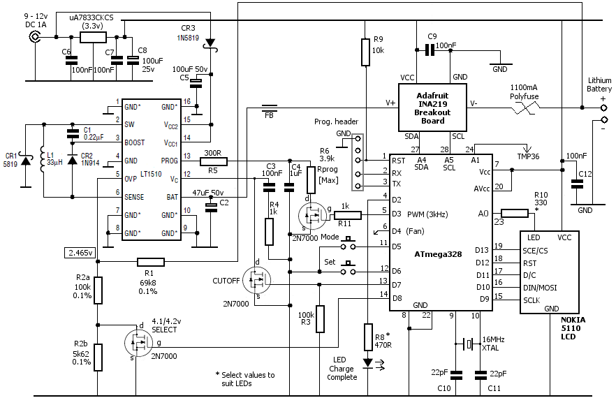
Since it doesn't look like anyone else is going to do it I completed the design, made a schematic , wrote the code, tested it, collected the data and took a screenshot of the scope monitoring the mosfet gate drive signal.

Now the post is complete and can be reproduced and replicated by anyone because it contains a "real" schematic (with component values) , data, code, and scope screenshot.
The circuit does , however , assume the op amp Subtractor exists to monitor voltage of the charging battery and control dac output accordingly. Attached code does not include that because I did not have the battery voltage monitor circuit at the time. I will update the software when I add that.


NOTE: There is an anomoly/"bug" with the current measurement code. I am attempting to "debug" this issue. Feel free to comment out that code in the mean time. The "bug" is that only the FIRST current measurement value printed is correct. All subsequent values are way off. I don't know what the cause is yet. S/W is not really my area of expertise so I may have done something stupid.

ALSO, I am currently adding the relay to the schematic. The code has already been updated to include the relay so the schematic is "lagging" the code at the moment. Sorry about that.

Constant_Current_Battery_Charger_Final_21.ino (1.88 KB)

Wow, you did a ton of work for this thread! I looked through some of your links. It looks like some of them are for Lithium chargers, which wouldn't be the same as NiMH.

Your final implementation looks like a CC charger for NiMH, but your results look like there's a problem. The charging current should follow the setpoint, but you're getting a big jump from 1600 to 1790. Your gate drive signal look like you're unstable as well.

Maybe the op amp is having difficultly driving the gate capacitance? The cartoons show a "gate driver" block for a reason, even though it's sometimes as simple as two resistors.

Unabreviated Table

12-bit Value (0 to 4095) Charging Current
1550 20 mA
1600 30 mA
1625 40 mA
1650 50 mA
1655 60 mA
1670 70 mA
1675 80 mA
1680 90 mA
1690 100 mA
1700 120 mA
1710 140 mA
1720 170 mA
1730 190 mA
1740 220 mA
1750 250 mA
1760 280 mA
1770 320 mA
1780 370 mA
1790 490 mA
1800 520 mA

That seems to be the entire working range.
I'm rebuilding the circuit now because I had problem when I added the op amp subtractor and the associated analogRead code and serial prints of the voltage read. I thought I must have plugged a wire in wrong somewhere or pulled one out but I completely lost regulation
(it was either OFF or 520 mA) I thought it must be hardware but when I went back to the older code with no serial prints or analogReads it followed the above table. I surmised that the feedback loop timing was critical and the serial prints resulted in too long a delay between feedback and correction because the serial print was in the middle. I tore the whole circuit apart and am starting over. I also have to add the relay for the SPDT function. I will say this though, the analogRead worked in so much as if the value read back was even 1 analog count over the maximum in my IF statement (not in the code I posted), it would turn off the fet completely. If it was < than the maximum , it would turn on the fet on FULL with 520 mA
charging current. I found a 50 mV/5A shunt at Halted Specialties yesterday for $6.50.