Big Size 20P COG ST75256 Displays Interfaced with Arduino

Hello all.

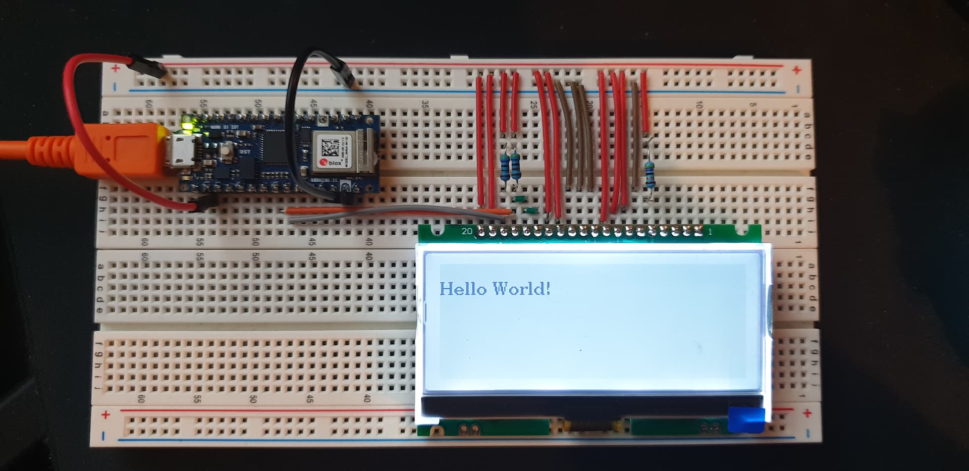
I am trying to interface a COG 256x96 with an Arduino Nano 33 IoT

Oriented on this display as it has nearly perfect dimensions for my project.

25696 ST75256 COG Display

The display is configured by the seller for 3.3v on I2C and I have tried a wiring indication supplied by the seller but no results. Reason for I2C is to save pins for other applications, but i will go for SPI if it becomes necessary.

My attempts were with the following constructor in U8g2 "Hello World" - "Page Buffer", in the hopes to get something on the screen. 16 bit is turned on in the library.

//U8G2_ST75256_JLX25664_1_2ND_HW_I2C u8g2(U8G2_R0, /* reset=*/ 8);	// Due, 2nd I2C, enable U8g2 16 bit mode for this display

Have tried the same constructor but with U8X8_PIN_NONE for reset.

Given that i am your perfect noob in arduino, does anyone have a wiring schematic / instruction to interface that display with the nano 33 iot on i2C or SPI?
Are there any changes that i need to do to the library?

Thank you for your help. :+1:


First off. I would choose a regular HW_I2C constructor e.g.

U8G2_ST75256_JLX256128_1_HW_I2C(rotation, [reset [, clock, data]]) [page buffer, size = 256 bytes]
  1. place the Arduino properly on the breadboard
  2. use the breadboard power rails as Nature intended. i.e. +3.3V and GND.
  3. connect the Display pins to the breadboard power rails with regular wire links cut to size.
  4. i.e. all VDD to +3.3V. all VSS to 0V (GND)
  5. connect 4k7 pullups to 3.3V on pins 17, 18 (SDA, SCK)
  6. connect 15, 16, 17 together.
  7. connect 5 (LEDA) to 3.3V with 47R resistor
  8. connect 17 to A4 (SDA) on the Arduino
  9. connect 18 to A5 (SCL) on the Arduino
  10. connect 9 (RST) to 3.3V with a 10k resistor

Run the U8g2lib examples with the above constructor.

The wiring scheme is shown in your link. i.e. which pin goes to VSS, VDD, ...
Get that correct on the breadboard i.e. so we can see the wires.

You only have 4 jumper wires from Arduino to breadboard. SDA, SCL, 3.3V, GND.

Untested. I don't have your display. Please report back.

The ST75256 only has 4 grayscale levels so it can't render black and white photos.
Anyway, U8g2lib does not support grayscale.

David.

1 Like

Hello @david_prentice , Thank you for taking the time.

I have followed your instructions but i do not have the same constructor in the examples for the library. I have the latest update for the libraries

The constructor that you have listed starts with "U2G2" but below you ask to run examples from U8g2lib. I have looked at the examples in both libraries and still did not find the a constructor for ST75256 JLX256128 on I2C.

When i copy the constructor from your post the console asks for a ")" in the line. Can i please know where you got the line from?

The only ones i have for 256128 are SPI

//U8G2_ST75256_JLX256128_F_4W_SW_SPI u8g2(U8G2_R0, /* clock=*/ 13, /* data=*/ 11, /* cs=*/ 10, /* dc=*/ 9, /* reset=*/ 8);	// Enable U8g2 16 bit mode for this display
//U8G2_ST75256_JLX256128_F_4W_HW_SPI u8g2(U8G2_R0, /* cs=*/ 10, /* dc=*/ 9, /* reset=*/ 8);		// Enable U8g2 16 bit mode for this display
//U8G2_ST75256_WO256X128_F_4W_SW_SPI u8g2(U8G2_R0, /* clock=*/ 13, /* data=*/ 11, /* cs=*/ 10, /* dc=*/ 9, /* reset=*/ 8);	// Enable U8g2 16 bit mode for this display
//U8G2_ST75256_WO256X128_F_4W_HW_SPI u8g2(U8G2_R0, /* cs=*/ 10, /* dc=*/ 9, /* reset=*/ 8);		// Enable U8g2 16 bit mode for this display
//U8G2_ST75256_JLX256128_F_4W_SW_SPI u8g2(U8G2_R0, /* clock=*/ 9, /* data=*/ 8, /* cs=*/ 7, /* dc=*/ 6, /* reset=*/ 5);  // MKR Zero, Enable U8g2 16 bit mode for this display
//U8G2_ST75256_JLX256128_F_4W_HW_SPI u8g2(U8G2_R0, /* cs=*/ 7, /* dc=*/ 6, /* reset=*/ 5);  // MKR Zero, Enable U8g2 16 bit mode for this display

I have tested with the constructor in my first post and nothing.
Tried without " 5. connect 4k7 pullups to 3.3V on pins 17, 18 (SDA, SCK)" no change.

The display does not react in any way. No flickering not dots no nothing,

I am not looking to display pictures, text will be enough.

(is this picture ok? i have used panorama mode to try and keep the wiring aligned)

Seriously. Invest in some plain single-core wire. It makes your breadboard readable to the rest of the world.

Simpler and neater wiring makes things work first time!

I got the constructor from the U8g2lib Wiki on GitHub.
The Wiki does not always agree with the Arduino Release.

You can try any of the regular HW_I2C constructors. I would avoid 2ND_HW_I2C

U8G2_ST75256_JLX25664_1_HW_I2C u8g2(U8G2_R0,  U8X8_PIN_NONE);

I presume that you have verified with an I2C_scanner.
It is possible that U8g2lib does not understand I2C on your Nano33

I will check with my Nano 33BLE (nRF52840 chip)
And with regular Zero (SAMD21 chip)

But I would be pretty confident that it knows SAMD21.

I must go out on my bike before it is dark.

David.

Yes, U8g2 works fine with Nano 33BLE and with Zero e.g.

U8G2_SSD1306_128X64_NONAME_1_HW_I2C u8g2(U8G2_R0, /* reset=*/ U8X8_PIN_NONE);

Yes, your photo in #3 looks as if everything is wired correctly.

The wiring would be simpler if you put the LCD in the "upper" e30 .. e11

Then you can have plain wire links to +3.3V rail and 0V rail e.g.

a30 ------ 3.3V  (LCD #20)
a29 ------ 3.3V
c28 4k7    3.3V
d28 yellow -> A5
c27 4k7    3.3V
d27 ------ d26
c26 ------ c25
d25 orange -> A4
...

You win plain wire links when you crop a resistor. Coloured wire links are better for complex wiring.

Most of your boards should be fine for the LCD. Except for the Nano Every which has horrible 5V logic.

David.

It is unlikely that you need the RST pin, but it is worth trying

U8G2_ST75256_JLX25664_1_HW_I2C u8g2(U8G2_R0, /* reset=*/ 8);

and connecting LCD_RST to digital#8 on your Nano33 IOT

The Wiki explains what 2ND_HW_I2C means e.g. https://github.com/olikraus/u8g2/wiki/u8g2setupcpp#communication

And it shows available constructors for ST75256 displays e.g. https://github.com/olikraus/u8g2/wiki/u8g2setupcpp#st75256-jlx25664-1

Yes, you need #define U8G2_16BIT because the display is 256 pixels wide.

As I said in #5 your wiring looks correct.
I would expect an I2C scanner to show 0x3C
I would expect the U8g2 examples to work even if the geometry is slightly wrong e.g. 256x64 driver on 256x96 hardware.

Regarding trans-reflective. "black text on white background" implies sunlight readability.
Obviously you need the backlight for night-time.
However sometimes it shows "better" with a backlight even in day-time.

The "white text on blue background" require backlight at all times. And don't look that nice at any time.

Hello @david_prentice

The display works after following your instructions.
Must define contrast, in my case 85

u8g2.setContrast(85);

The only constructor that works is:

U8G2_ST75256_JLX25664_1_HW_I2C u8g2(U8G2_R0, /* reset=*/ 8);

The the other variants work as well, 2 and F.
Constructors work both with digital#8 or U8X8_PIN_NONE for the reset pin.

Software variants are not really good for changing text. Everything gets overlapped.

I have tried other constructors to see if i can get the full height of the screen as at the moment the active area starts at pixel 32, but

U8G2_ST75256_JLX19296_1_HW_I2C

does not work at all with any variants.

Is there a way to alter the library or "force" the height in any way?
Or is this something that only @olikraus can resolve?

An i2C scanner gives the result:

00:21:12.830 -> 
00:21:17.835 -> Scanning...
00:21:17.883 -> I2C device found at address 0x3C  !
00:21:17.883 -> I2C device found at address 0x60  !
00:21:17.883 -> I2C device found at address 0x6A  !
00:21:17.883 -> done
00:21:17.883 -> 
00:21:22.888 -> Scanning...
00:21:22.888 -> I2C device found at address 0x60  !
00:21:22.888 -> I2C device found at address 0x6A  !
00:21:22.888 -> done


Somehow my brain needs to see a wire between links. I do not know how to explain it.


Since the Nano 33 IoT is 3.3v , is there an absolute need for any of the resistors?

I have removed the pullup connections for 17 and 18 and the display worked fine.

Connect 4k7 pullups to 3.3V on pins 17, 18 (SDA, SCK)


The code used is:

#include <Arduino.h>
#include <U8g2lib.h>

#ifdef U8X8_HAVE_HW_SPI
#include <SPI.h>
#endif
#ifdef U8X8_HAVE_HW_I2C
#include <Wire.h>
#endif

U8G2_ST75256_JLX25664_F_HW_I2C u8g2(U8G2_R0, /* reset=*/ 8);

void setup(void) {
  u8g2.begin();  
  u8g2.setContrast(85);
}
void loop(void) {
   u8g2.clearBuffer();         // clear the internal memory
  u8g2.setFont(u8g2_font_ncenB08_tr); // choose a suitable font
  u8g2.drawStr(0,10,"Hello World!");  // write something to the internal memory
  u8g2.sendBuffer();          // transfer internal memory to the display
  delay(1000);  
}

Sorry to have been so pedantic. It is always wise to start "conservatively". I suggested short plain wire links because I did not know if you owned any coloured single core wire. Your photos show a beautifully neat breadboard. A fine example to anyone having difficulty with "lots of pins".

I assume that your wiring has always been correct. Just needed to use the regular HW_I2C constructor.

I would expect the full-fat 256160 constructor to work. But with only 96 visible rows.
You need to make several changes to the U8g2lib library code for a specific 256x96 constructor.
You should persevere with 256x160 first.

Meanwhile, I have been intrigued. So I have ordered a 256x96 display for myself.
When it arrives, I will obviously write / adapt a suitable constructor.
I will either offer a Pull Request to Oliver. He might add it to his next Release.

Your Nano33_IOT has "other" I2C devices 0x60, 0x6A.
Which means it already has pullups on SDA, SCL. You can omit the 4k7s
Your "other" boards might not have I2C pullups.
You can omit the 10k pullup on LCD_RST. See if it works with U8X8_PIN_NONE.
You can always omit 10k if you are using program control e.g. LCD_RST --> digital#8.
You can replace the 47R with 39R .. 0R. See which gives suitable backlight.

When you have chosen the "best" backlight you can try the display in bright sunlight i.e. with and without backlight.
Offer advice to the recent enquiry.

David.

1 Like

I did not have the solid wires, long live amazon and their prime delivery.

I'll start with the 256x160 tonight and post the results.

I have 2 of the 256x96, i do not mind sending you one.

Did not forget about the other post. Will reply promptly.

My display might take 14-21 days to arrive from China. You never know !!

If we are both in the UK it is practical to mail it "quicker". But a recent packet to Germany took 14 days. i.e. just as long as China.

So I suggest that you just investigate the 256160 constructors first.
Your Nano33 has enough SRAM for a full _F_ 5kB monochrome buffer.

It even has enough SRAM for a 10kB full 4-grayscale buffer. (Even though U8g2 does not support grayscale)

David.

Then the least i can do is to pay for that display.

Please PM me your paypal.

You said in a previous post that you wanted to take the bike out before dark... my best friend is a biker as well, did not see him in many years. Please do not put my puny display before riding your bike.

We are both in UK. So if you can still cancel, let me know the address and i will post it on Friday via Saturday guarantee.

By the way, that is a good seller, they've tried to help. I have asked them to post my pictures and the link to this thread on their listing. Hopefully it will help others.

I somehow stopped reading Arduino Forum... but it looks like I get notified if someone references me. Still sooo happy that David takes care :slight_smile:

Just create an issue here Issues · olikraus/u8g2 · GitHub and i think we can get it done together. Pull request is also fine, but it is a little bit tricky due to the semi automatic code constructions.

Oliver

Hello All.

So, both displays work now. I kept the wiring just to make sure.

The 256x96 works with the constructors for 256x160, just offset the screen downwards.
If the first line of text is size 8, start the line at 73:

u8g2.drawStr(0,73,"Hello World!");

The main thing to remember is that the contrast for these constructors is different.

U8G2_ST75256_JLX256160_F_HW_I2C u8g2(U8G2_R0, /* reset=*/ U8X8_PIN_NONE);

~Contrast on both displays works at 150 for 256x96 and 178 for 256x160 (at least in my case).

I would like to propose when starting new displays to actually test with the " ContrastTest.ino" from

https://github.com/olikraus/u8g2/blob/master/sys/arduino/u8g2_page_buffer/ContrastTest/ContrastTest.ino

The ContrastTest will move the contrast across all the range and all the active area of the screen so it is easy to see if it works or not.

The current consumption for the displays is:

Display Current Backlight
256x160 23.5mA Yes
256x160 10.9mA Yes with 47R
256x160 2.6mA No
256x96 13.9mA Yes
256x96 7.6mA Yes with 47R
256x96 1.06m No

Easily readable in intense light. Tested with a work light which is probably brighter than the sun in UK at this time of the year.


If you were still interested in the SPI configuration, I have got it working with the following wiring ,with an ESP-32;

I have also made a schematic for the I2C configuration, per David's instructions;

This topic was automatically closed 180 days after the last reply. New replies are no longer allowed.