I have just destroyed an Arduino Nano, and an Arduino Uno and am looking for help in telling me what I may have done wrong.
The Uno worked fine whilst connected to the breadboard and powered from the USB supply, but didn't last long when I soldered it into a more permanent situation.
The Nano was the first to fail, it was powered from 12V. I then created a regulated 8V supply from the 12V supply and fed that into the Uno's VIN pin. It lasted only seconds before failing as well.
Since it worked fine when powered from the USB supply, I assumed that switching to the VIN power is the cause of the failures.
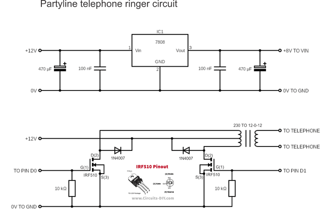
The project is a party line telephone ringer.
As a new user, I can't upload attachments, but I do have available the sketch and the circuit diagram for the external components.
You should be able to post attachments, links and images now. Many forum members read the forum using smartphones & tablets, so bear that in mind if you post attachments. Anyone can see links & images. Post your sketch as part of your reply, using code tags </>
Thank you all for this. Hopefully I'll get this right. This is the sketch:
/* Partyline telephone ringer
  This will ring a telephone with various ring cadences
  which may include the standard UK and US rings as well
  as a number of partyline rings.
  The number of different cadences is controlled by
  push buttons - so the number depends on the number
  of buttons installed.
*/

//setup pins for ringing output
const int ringPin1 = 0;
const int ringPin2 = 1;

// setup pins for pushbuttons
// Depending on which Arduino is used, these may need
// to be changed.  Also, there may not be enough
// digital pins available
// make sure to comment out the pinModes in setup
// as well
// Buttons connected between the respective pin and GND
const int PBNZ = 2;
const int PBUS = 3;
const int PBPA = 4;
const int PBPD = 5;
const int PBPR = 6;
const int PBPS = 7;
const int PBPJ = 8;
const int PBPK = 9;
const int PBPU = 10;
const int PBPW = 11;
const int PBPX = 12;
const int PBRO = 13;

const int TEST = 14;  // test pin for continuous ringing


// define variable for setting length of short ring
// long ring and NZ and US rings.  300mS should be about
// right for the short ring, and a long ring 900mS
// this number is the number of cycles, so at a frequency
// 20Hz, and a length of 300mS, there are 6 cycles
// and at 900mS, 18 cycles.
// At 20Hz, each cycle is 50mS
unsigned shortring = 6;
unsigned longring = 18;
unsigned shortpause = 200;
unsigned longpause = 2000;
unsigned NZring = 8;  // NZ ring is 400 mS
unsigned USring = 40;  // US ring is 2000mS
// define variable for setting frequency of ring
// e.g. for 20Hz, one cycle is 50mS, half cycle is 25mS
// this number is the length of one half cycle.
unsigned frequency = 25;
// declare variable used in subroutine
unsigned count = 1;


void setup() {
  // setup pin 2 for the ringing output
  pinMode(ringPin1, OUTPUT);
  pinMode(ringPin2, OUTPUT);

  // setup the pins for the cadences
  // The partyline codes are morse codes, for
  // either 5 or 10 parties.  The codes used are
  // A (.-), D (-..), M (--), R (.-.), S (...)
  // for a five party line and these five:
  // J (.---), K (-.-), U (..-), W (.--), X (-..-)
  // as well for ten party lines.
  pinMode(PBNZ, INPUT_PULLUP); // standard cadence is 400 on 200 off 400 on 2000 off
  pinMode(PBUS, INPUT_PULLUP); // standard cadence is 2000 on 4000 off
  pinMode(PBPA, INPUT_PULLUP);
  pinMode(PBPD, INPUT_PULLUP);
  pinMode(PBPR, INPUT_PULLUP);
  pinMode(PBPS, INPUT_PULLUP);
  pinMode(PBPJ, INPUT_PULLUP);
  pinMode(PBPK, INPUT_PULLUP);
  pinMode(PBPU, INPUT_PULLUP);
  pinMode(PBPW, INPUT_PULLUP);
  pinMode(PBPX, INPUT_PULLUP);
  pinMode(PBRO, INPUT_PULLUP); // Ring-off at end of call

  pinMode(TEST, INPUT_PULLUP); // test pin for continuous ring
}

void loop() {
  if (digitalRead(PBNZ) == LOW) {
    Ringing(NZring);
    delay(shortpause);
    Ringing(NZring);
    delay(longpause);
  }

  if (digitalRead(PBUS) == LOW) {
    Ringing(USring);
    delay(longpause); // Since pause between rings for US is 4000mS, repeat this
    delay(longpause);
  }

  if (digitalRead(PBPA) == LOW) {
    Ringing(shortring);
    delay(shortpause);
    Ringing(longring);
    delay(longpause);
  }
  if (digitalRead(PBPD) == LOW) {
    Ringing(longring);
    delay(shortpause);
    Ringing(shortring);
    delay(shortpause);
    Ringing(shortring);
    delay(longpause);
  }

  if (digitalRead(PBPR) == LOW) {
    Ringing(shortring);
    delay(shortpause);
    Ringing(longring);
    delay(shortpause);
    Ringing(shortring);
    delay(longpause);
  }

  if (digitalRead(PBPS) == LOW) {
    Ringing(shortring);
    delay(shortpause);
    Ringing(shortring);
    delay(shortpause);
    Ringing(shortring);
    delay(longpause);
  }

  if (digitalRead(PBPJ) == LOW) {
    Ringing(shortring);
    delay(shortpause);
    Ringing(longring);
    delay(shortpause);
    Ringing(longring);
    delay(shortpause);
    Ringing(longring);
    delay(longpause);
  }

  if (digitalRead(PBPK) == LOW) {
    Ringing(longring);
    delay(shortpause);
    Ringing(shortring);
    delay(shortpause);
    Ringing(longring);
    delay(longpause);
  }

  if (digitalRead(PBPU) == LOW) {
    Ringing(shortring);
    delay(shortpause);
    Ringing(shortring);
    delay(shortpause);
    Ringing(longring);
    delay(longpause);
  }

  if (digitalRead(PBPW) == LOW) {
    Ringing(shortring);
    delay(shortpause);
    Ringing(longring);
    delay(shortpause);
    Ringing(longring);
    delay(longpause);
  }

  if (digitalRead(PBPX) == LOW) {
    Ringing(longring);
    delay(shortpause);
    Ringing(shortring);
    delay(shortpause);
    Ringing(shortring);
    delay(shortpause);
    Ringing(longring);
    delay(longpause);
  }

  if (digitalRead(PBRO) == LOW) {
    Ringing(shortring);
    delay(longpause);
    delay(longpause);
  }

  if (digitalRead(TEST) == LOW) {
    Ringing(longring);
  }
}

void Ringing(int length) {
  count = 0;
  while (count < length) {
    digitalWrite(LED_BUILTIN, HIGH);   // turn the LED on (HIGH is the voltage level)
    digitalWrite(ringPin1, LOW);
    digitalWrite(ringPin2, HIGH);
    delay(frequency);
    digitalWrite(LED_BUILTIN, LOW);    // turn the LED off by making the voltage LOW
    digitalWrite(ringPin2, LOW);
    digitalWrite(ringPin1, HIGH);
    delay(frequency);
    count++;
  }
  digitalWrite(ringPin1, LOW); // ensure both pins are LOW at end of ringing cycle
}
Hi,
Can you please post image(s) of your PCB or what ever you soldered the Nano/UNO to?
Have you put header sockets on your board and then just plugged the Nano or UNO into it?
A full schematic would be appreciated, please include all power supplies, component names and pin labels.
Well I worked in a telephone exchange. The line circuit is disconnected during the time when the ring voltage is applied. So this circuit can burn things in the exchange.
If they ever find out, "ask not for whom the Bell tolls"
Thank you for all your input, it's great to see such interest.
To those concerned about the use: it's for a theatre play. It will not be connected to any working telephone lines. I worked as a telephone technician for 20 years, so am familiar with the requirements.
I'll take some pictures and make a few more drawings today.
It's the de-regulation. They made a lot of illegal things legal, but offloading the responsibility for all the equipment and wiring at the user premises, to the user. The access box is the phone company's "line of defence" as they can disconnect everything you have there, and prove which side it's on.
With that arrangement, they mainly don't have to care what you do to your lines. If you mess up their stuff too many times, I suppose they would just refuse to serve you.
I remember the days when it was illegal to disconnect a phone.