Hello,
Im trying to understand this circuit.
I need to understand how it works, how it charge a battery 18650
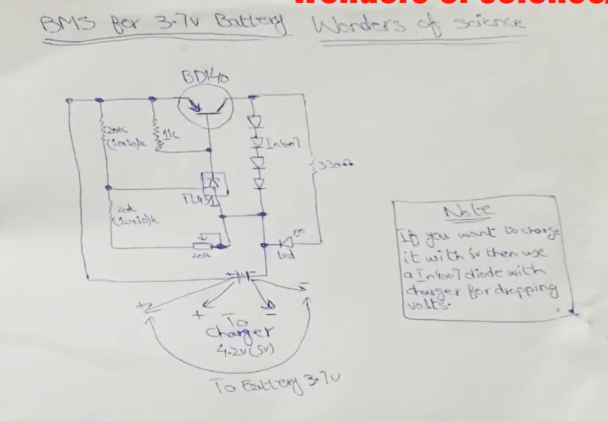
I supose that the first stage is the TL431, I understand that it create a voltaje reference of 2.5v to regulate a output voltage. Then between anode and cathode flow a small current that activate the transistor.
when battery is discharge the circuit start to charge, when stop ?
when stop disipate the load throught the diodes ?
The TL431 is normally used as 2.5volt reference, but that voltage can be changed with external resistors.
R1, R3/R4 (across the cell) just do that, to ~4.2volt (adjustable with R4).
If battery voltage is >= 4.2volt, the TL431 starts to conduct, and drives the base of the BD140, that drives a load on it's collector. R5/LED is a visual indicator of that. The load is not just a resistor, but four diodes in series. Constant voltages across the transistor and diodes, (almost) independent of discharge current.
Leo..
Its a load-balance circuit. The circuit is drawn in a very awkward configuration so its very hard to read,
I've reworked it below.
The charging current flows through the cells which are in series. When individual cells reach the
full voltage the balance circuit for that cell acts as a shunt regulator and shunts excess current
through the BD140 and diodes to prevent the cell over-charging. The diodes create enough
voltage drop to light the LED consistently and help disipate some of the heat that would otherwise
be generated in the transistor.
If DC source and battery are in the same line, sources must be add ?
if the battery is discharger must have around 3.7V, I we use a 4.2 dc source the difference is around 0.5V ???
Two voltage sources will fight and draw huge currents if connected together, unless current limiting
is implemented. Chargers implement current limiting, so that the voltage will drop as needed to limit
the max current to the limit.
It seems, from your notes, that you want to use a BMS circuit for just one cell.
You don't.
BMS circuits are for strings of cells, to prevent overcharging of one cell in the string.
The string is then connected to a 8.4volt/12.6volt/16.8volt/etc. charger (depending on the number of cells).
For one cell, you just use a single cell charger.
Tell us what you're really trying to do.
Leo..
I am trying to design a BMS, I know that a BMS is much more than just charge a battery, I need measure voltage and current to prevent over Charge or over discharge, balancing and other things.
I just want to understand how this circuit works in the charge work.
because I read many information that talk about 2 stages at least in the work to charge a battery.
CC and CV, But i'm not very ensure how it works, I have seen circuit with LM317, other many circuits with TL431 I supose that this work can be made with op amp, etc.
But in this case I want to understand how works this circuit, I see that the autor use it to balance the batteries, and just prevent overcharge.
I dont understand what is the real work of the TL431 and the transistor, and I dont know what do the R2
Bleed resistor for the TL431.
R2 ensures the BD140 stays fully 'off' when the cell voltage is below 4.2volt.
I think that with your current level of knowledge you should NOT try to design a LiPo battery charging circuit.
Getting it wrong could result in exploding batteries.
Leo..
Not sure what you mean there.
If you connect a voltage source (or load) to a battery, then both voltages are about the same.
When current flows, there could be a small voltage drop across the wires, but hopefully less than 0.5volt.
LiPo battery voltage can be anything between 3volt and 4.2volt, depending on the state of charge.
If the battery is partially charged, say 3.7volt, the charger should limit it's current, to say 1Amp.
When the battery is nearing 4.1volt, the charger should reduce current until it's zero at 4.2volt.
A complex chip is usually needed to do this right. An LM317 is certainly not suited for that.
Leo..
In this particular circuit.
In the base of the circuit appears that the charger (Dc source 4.2V) and the Battery 3.7 (discharged) are connected to the same terminals.
let me understand, if I have both connected in the same terminal, the voltage that feed the entire circuit is 4.2 + 3.7 ???
A "4.2volt charger" does not mean it's always 4.2volt.
The moment you connect the charger to that 3.7volt battery, charger voltage drops to 3.7volt.
The charger is then in constant current mode, and pumps say a constant 1Amp into the battery.
Battery voltage slowly rises (minutes/hours) until voltage is about 4volt.
Then the charger reduces it's current, until it stops at 4.2volt (voltage mode).
Leo..
i34a23:
But what about the dc source and battery connected in the same line, those two sources produce a drop voltage of 0.5 V ??
The charger will act as a constant current source until the current drops below a threshold. A current source
will simply comply with the load of the cell/battery. This is what current limiting is.
Then the current flow through the battery loading it.
when the voltage battery rise from the 4V, the reference voltage for the TL431 is get and the TL431 works as a shunt, derivating the current to the transistor load, and we can see the RED LED glow
Yes I know that BMS is very complex.
but I wondering some about charge process.
I supose that it circuit is only a overcharge protection, but it will not help with the stage of CV.
on CV the current is decreacing, this process must be controlled for a external device such a microcontroller ??? this is a defined function ?
Simple chargers are voltage sources with a current limit. The voltage is set to the trickle-charge value, the
limit to a charge current (fast, or normal).
More complicated chargers sense the voltage regularly and ramp down the current setting to be gentler on
the battery and prolong its life. They also switch off once its fully charged (trickle charging isn't that good
for many chemistries). So they have a timer, voltage sense mode as well as set voltage and current limits.
You can also have battery temperature sensing, cooling, cell diagnostics and so forth.