I have been working on a model rocket flight computer, everything on it has worked except a BNO085 sensor fusion chip. I have it connected over UART to a Teensy 3.6 built onto the board via TX1/RX1, but the chip never starts streaming data, it looks like the code finds the chip but never starts streaming data. I can't seem to find anything wrong with my schematic or code, so thats why im here. Here is my schematic and code.
R39 is 10K, forgot to label that.
Usually a serial Tx goes to a serial Rx and a serial Rx goes to a serial Tx; based on the names of the labels of the nets you have swapped it around (but I can't be sure as I do not know where Tx1 and Rx1 go to).
In your loop, you check if the rvc.read(&heading) function returns false, and if so, the function exits. If this function repeatedly returns false, it can indicate an issue with the sensor not responding or improper communication settings.
Since it is a custom PCB, you have to check it with a multimeter.
The pcb layout is PACKED with traces because i have a Teensy 3.6, BMI270, BMP390, and 6 others chips built on to a quite small pcb so it would be quite hard to see where the traces are, i can still show it if you would like though. I had a small suspicion it was noise from all the traces, but all the other chips work fine so i don't think so.
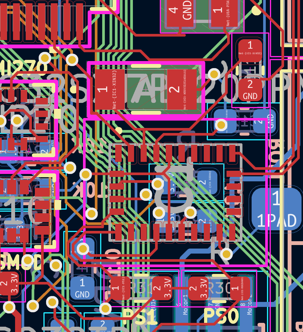
Here is the chip on the pcb layout. I have used this chip before on an older flight computer using the Adafruit breakout. This is my 3rd prototype the Teensy 3.6 is a little unstable for some reason. And yes i have tried running it with the plane code just to talk to the 085 with no luck.
Hi,
I note your PCB pattern is not the full PCB.
Do you have a gnd plane or decent area that is a gnd reference?
Okay, so you need to do some breadboarding, not using your PCB to prove you have communication with the 085.
Do you know if the crystal on the 085 is oscillating, the two 22pF capacitors connected to it do not look as though they go to a gnd plane, but to gnd through some thin tracks.
The gnd connection for the 22pF caps in my mind should go to gnd pins on the 085.
So layout could be a problem.
Yup. Some kind of noise issue is likely. Taking the oscillator net through a via is not a good idea. Forking an oscillator net is also not a good idea. Having no GND plane underneath and around the oscillator is not a good idea. And that's just the situation concerning this little bit. However, even with this layout, I'd expect the BN0085 to do something.
However, I noticed this:
Which you responded to with this:
It still raises the question with me where the TX1 and RX1 nets go. Supposedly to the Teensy. Hopefully not the TX1 resp. RX1 ports on the Teensy, as that would indeed imply you swapped the pins. The BN0085's TX pin needs to go to an RX pin on the microcontroller. After all, one side sends, the other side receives on the same line. And vice versa. Are you sure you've got this right?
So i made another version of this flight computer but switched the communication method to I2C, and switched the the schematic to Sparkfun's BNO086 schematic and now it works, the schematic was barely different and the pcb design stayed almost the same. Very strange why this didn't work.