... the frequency is very high.
And the point is?
... the frequency is very high.
And the point is?
Well in any case the you need +/- supplies for both amplifiers.
Your ADA4899 need an input resistor otherwise the gain will be ONE
The higher the frequency, the lower the impedance...
This IC seems to have some input capacity... (like any electronic device).
Therefore, not best choice for very high frequencies.
But will be less prone to very high freq ossilations...
I've never seen that before for an op-amp
Why is it necessary to have DISABLE = NC?
The input resistance and capacitance are given in the tables.
It's a confusing parameter.
Because the sensor frequency is between 100 and 900KhZ. It needs an amp that can handles such high frequencies.
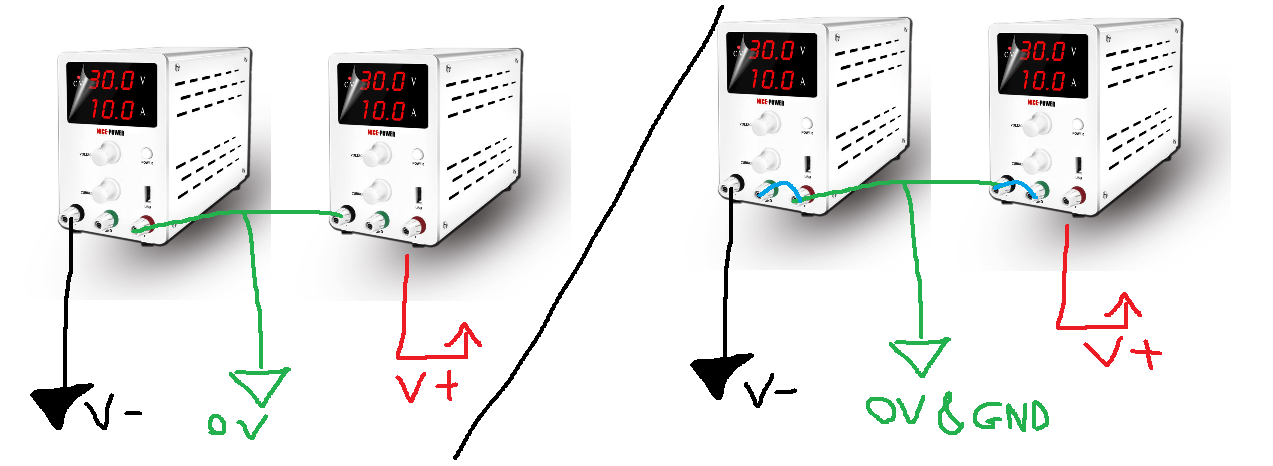
Already tried this with the buffer, using two power supplies combined to make +/- power supply. Still getting weird values.. The output is not tracking the input.. there's an offset that is changing when increasing or decreasing the input values.
For a real circuit or your proteus simulator?
The point is to use a buffer before that amplifer. The buffer will give a small impedance value at its output which can used by the amplifier to allow high frequencies
Don't connect the GND terminals on the power supplies/
What power supply voltage are you using?
What is the input signal voltage range?
At 1 MHz impedance is still 30 kohm...
If that is too low: find a high freq. IC.
I tried both connected and disconnected GND, same result.
I also tried diff power supply voltage from 3v to +18v, the output offset is changing but its not the same as the input.
The input signal voltage range is shown below, its -13v +13V.
I wanted to add that for the input voltage, I am using the same power supply for powering the buffer via a voltage divider to reduce the voltage ( from 3 to 5v).
I want to know the voltage YOU are applying to the buffer input
The input signal range must be at least 2.2V less than the power supply voltage.
So if the power supply voltage is 5V then the input signal MUST be less than
5 - 2.2 = 2.8V
I applied different voltages starting from 3v to 5v.
Ah! I will try again taking this into consideration, thanks! I'll be back with new experiments results.
Hello,
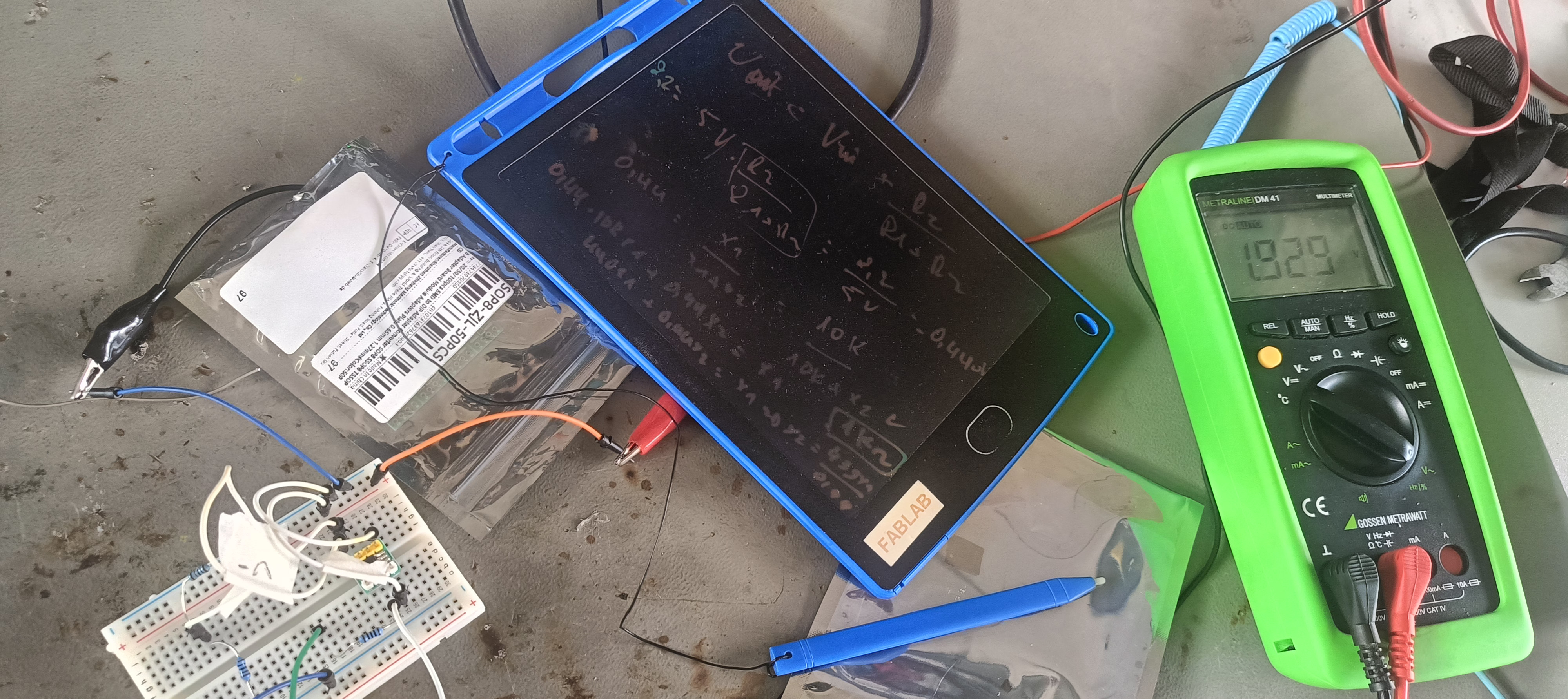
After modifying the input value to 0.7v, the corresponding output value is shown in the figure below :
Knowing that the grounds of the power supplies are not connected. Both power supplies values indicates 5v. Furthermore, whether the input signal is connected or not, the output remains the same. That's weird!