I am having a hard time trying to setup an eletric guitar frequency reader, I'm following the circuit from the following website: [https://www.instructables.com/Arduino-Guitar-Tuner/]
but with some differences, but with some differences which are that I'm using a 12 volt supply for the amp instead of 2 9v batteries which is a tl082 and just serial printing the frequencies on serial monitor instead of lighting leds.
I am getting 1.5 volts aproximately in the opamp output and the frequencies are shown 2.080 hz, I believe that i am doing something wrong with the opamp because I am really new to this component.
Normally, op-amps use dual (positive and negative) power supplies. You can use a single supply but you have to bias the input instead of the output. (I don't have a handy schematic for you.) Or if the circuit has gain it might be best to bias both the input and output.
It's also a bit "dangerous" to potentially send more than 5V (or negative voltage) into the Arduino. Voltage Protection Circuits
The 12V and Arduino need to have a common ground. so the - of the 12V needs to connect to the - of the arduino.
Also a TL082 is NOT rail-rail compatible. Look at the table you will find here and choose one that is, or (as shown in the original circuit) use two batteries.
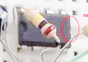
You have wired the power to the op amp backwards. Pin 4 should be the negative and Pin 8 should be the positive.
There is so much other stuff totally wrong, but as a Frtizing layout diagram is utterly useless, it is hard to see what you are actually doing. The language of electronics is a schematic, not a physical layout diagram.
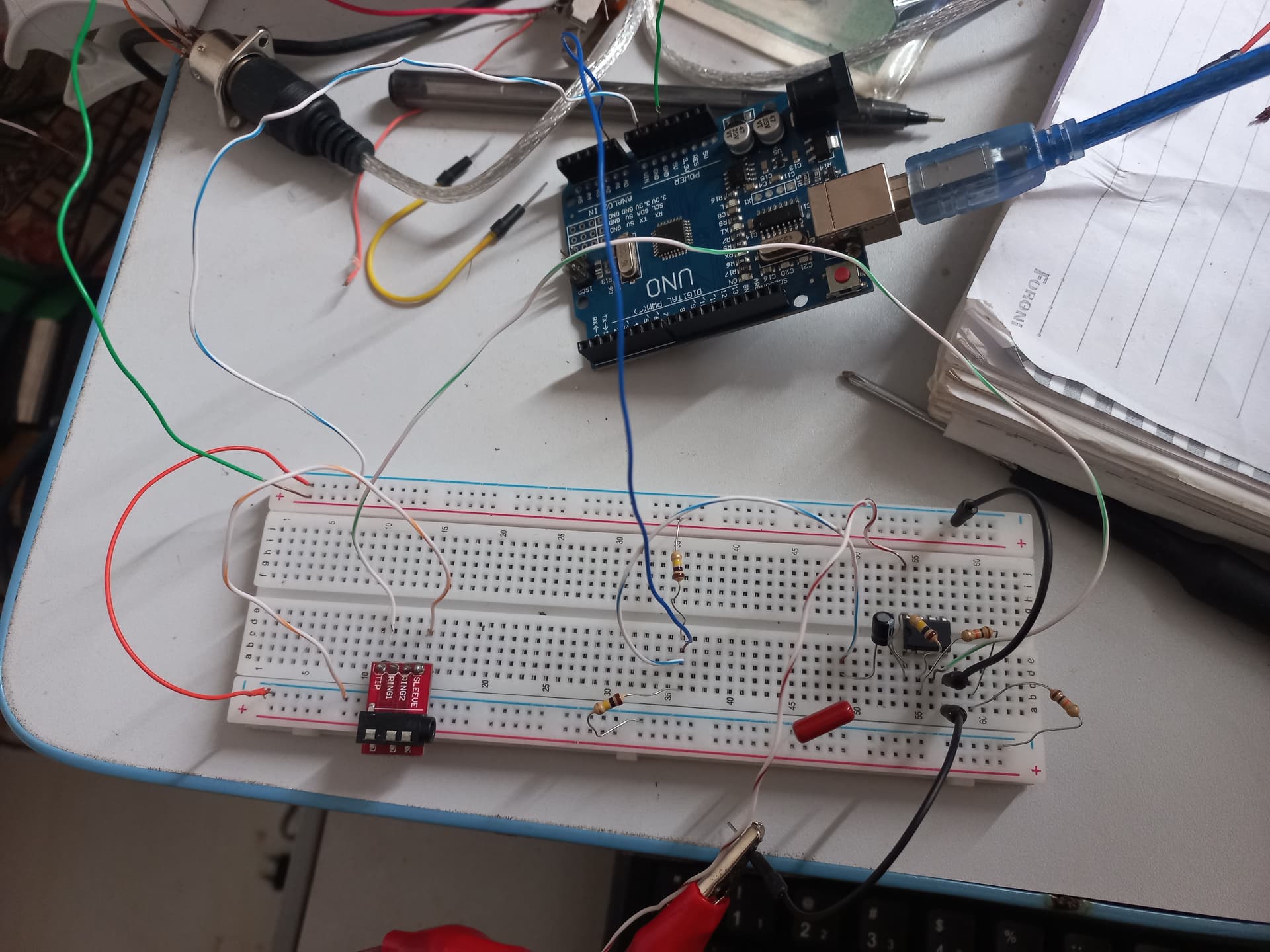
Can you post some images of your project?
So we can see your component layout.
How have you got it connected.
The reason for two 9V supplies is to give a positive and negative supply to the op-amps.
The junction of the two is connected to circuit gnd.
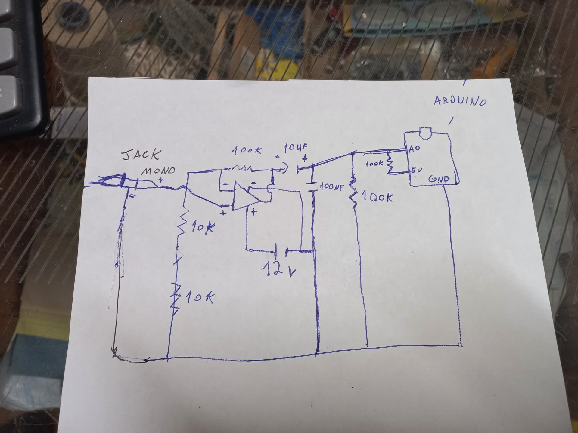
Can you please post a copy of your circuit, a picture of a hand drawn circuit in jpg, png?
Hand drawn and photographed is perfectly acceptable.
Please include ALL hardware, power supplies, component names and pin labels.
Reverse engineer your project and draw a proper schematic.
I will try the 9v batteries, but even if it works i will need some alternative to get this thing working without two 9v bateries, I forgot to say that I tested with lm358 op-amp too and had same result
Can you please tell us your electronics, programming, arduino, hardware experience?
Your 12V supply is not referenced to the circuits gnd, the two 9V batteries are.
They supply +9v and -9V to the TL082 with respect to signal gnd.
Signal gnd is use for the input and output reference of the pre-amplifier.
Very good idea, use your DMM to measure the voltages around the pre-amp in 2 x 9V configuration.
As this is a tuner, not turned on for long periods of time, the original designer has seen economy in using 9V batteries.
What is your application?
Sorry for the mess but I don't had much time to work properly in this.
for the 12v power I am using an ATX power supply, I am using 2 10k resistor in series for the 5v divisor.
the Code I am using: `#define ANALOG_PIN A0
#define THRESHOLD 512
#define SAMPLE_TIME 1000 // Tempo de amostragem em milissegundos

void setup() {
  Serial.begin(115200);
}

void loop() {
  unsigned long startTime = millis();
  int lastReading = analogRead(ANALOG_PIN);
  int currentReading;
  int zeroCrossings = 0;

  while (millis() - startTime < SAMPLE_TIME) {
    currentReading = analogRead(ANALOG_PIN);

    // Verificar se houve um cruzamento pelo zero
    if ((lastReading < THRESHOLD && currentReading >= THRESHOLD) ||
        (lastReading >= THRESHOLD && currentReading < THRESHOLD)) {
      zeroCrossings++;
    }
    lastReading = currentReading;
  }

  // A frequência é metade do número de zero-crossings por segundo
  float frequency = (zeroCrossings / 2.0) / (SAMPLE_TIME / 1000.0);

  Serial.print("Frequency: ");
  Serial.println(frequency);

  delay(1000); // Esperar 1 segundo antes da próxima leitura
}
Sometimes i am getting more than 5v in the output of the pre amp
Why are you angry?? @TomGeorge just posted the wiring diagram from the site that I mentioned in the op which i am already based on, and no I am not wiring ground and vcc wrongly look at my picture of breadboard...
Because you appear to be saying everything is alright when it is everything but alright. You don't seem to be listening.
The brutal truth is that the vast majority of what is posted on the instructables web site is rubbish. It is posted by people who think they know a lot more than they do. So for you to reject the advice you are getting here is very frustrating. Given where this project is, it is going to perform in a rubbish way as well. They are well known for it.
The basic idea that you have a dual operation amplifier and you ignore one, not even wiring it up, while the other one has a very high gain is simply fundamentally wrong, and asking for problems.
All operation amplifiers need a split supply, some times called a dual supply. With only a single power supply you need some way of creating a mid way voltage point known as a virtual ground.
That is what @runaway_pancake showed you how to do in his post #17. The resistors R3 and R4 provide a mid rail point or virtual ground, for the other signals to pivot around.
This technique can be applied to any operational amplifier. Personally I would put a 10uF and 0.1uF ceramic capacitor across each of R2 & R3 to make this virtual ground a bit more robust and stable.
However, in your case you need a virtual ground like this and a way to reduce your 12V signal into a 5V peak to peak signal centered or shifted down to 2.5V so as not to damage your Arduino.
This link shows you how you can achieve this using operational amplifiers.
Note this is in addition to any operational amplifiers you will need to boost the very small signal you get from the guitar's pickups so that it is about 5V peak to peak.
The other thing about the successive links (rabbit holes) from the original article you were trying to follow, is that the author of the frequency measurements is very concerned about not getting clipping on the input waveform. Where as the way the signal's period is measured will work a lot better when the signal is clipped. You see what I mean about instructables being full of fundamental mistakes.
Your schematic in post #17 has a lot wrong with it.
there is no capacitor on the operational amplifiers input to remove the DC bias from your source.
the mid point from your virtual ground using the 10K resistors is not wired to anywhere.
but you do get a virtual ground from your two 100K resistors for the Arduino but it is not wired to the operational amplifiers where it is needed.
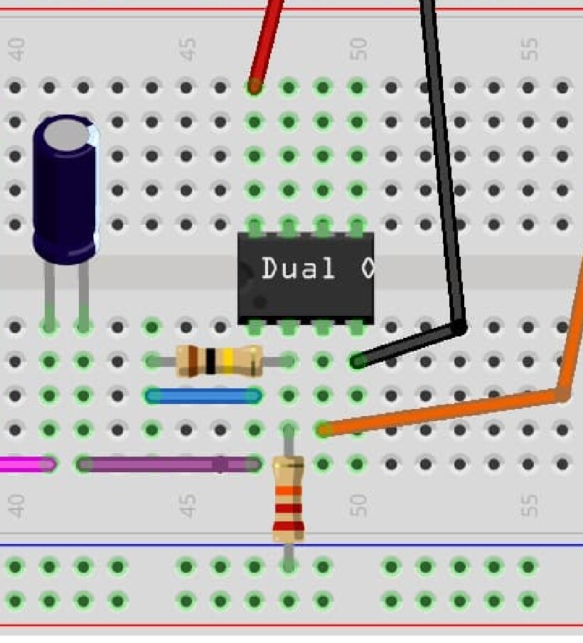
Because of the angle the photo was taken from and the underexposure. However, we can fix that up well enough to get clarity on the matter:
The white "O" artefact in the wiring diagram is probably the first letter of the word "Opamp", with the rest cut off because it didn't fit onto the component shape.
#26 is an excellent suggestion by @runaway_pancake and the obvious solution for OP.