@PaulRB:
No. Please listen to what I'm telling you. If you can't understand, please ask me to clarify. Otherwise please let me know my advice is not wanted. 1 digital output, 4 analog inputs. Corrosion due to current flow will not be a problem because the current flows for < 1ms every 15 mins.
I'm appreciating your help greatly, but I was focused on the corrosion problem (I might have thrown around the word electrolysis accidentally. Thanks @wmarle for correcting me) and I was under the impression that using your method wouldn't solve that. Particularly as for testing waiting 15 minutes in between readings will kill me!
Don't use Arduono pin D1, it is needed for sketch upload & serial comms with the PC.
Noted, but out of curiousity, why do they have it available if it's used for that? Can it be used for trouble shooting or something?
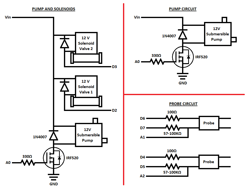
Are you planning to have two pumps?
No. You're absolutely correct, I just left the original pump only drawing there for reference. I'll clean up the drawing and reupload once I clarify:
That 10K will prevent the pump from working. You need a 10K pull-down on the Arduino pin controlling the mosfet.
The arduino pin is the one currently marked as D1 then? As in replace the 330K resistor? I looked up pull down resistors and found this which seemed to indicate that a pulldown had to be attached to the ground.
If you can't find anything lower cost & power, you might as well have 2 or 3 pumps.
I'm going to look around some more, they are exactly the same price. I went ahead with them because for me this as much a learning project as a practical project. When I read your sentence I thought... wait... you just bought a valve for the same price as the pump! Definitely going to have to work on the acquisition portion of my skillset.
@wmarle:
Pumps, solenoids, etc. have to be powered separately, or from an external power supply
I'll do a little research on this before I start picking apart your brain on the separate power supplies thing. I really wish I could sit down with an electronic engineer and understand all of this. I keep getting lost along the way. Once I have a draft revised circuit I'll post it up for review with all the changes above and this part.
I was reallllly hoping to have this whole system powered from one power supply though as I only have one available power socket and I don't want to rely on a battery pack (Though I want to build it that way as well for learning purposes).
Regarding the level sensor. I would imagine I would have to turn it on right before the pump switches on to take a level check and keep it on as long as the pump is on to ensure the level doesn't drop below the threshhold. If the level does drop I would also need it sporadically turn it on to check if I've refilled the water trough to allow pump function again.
I can deal with this at the code level once the whole circuit is a beautiful efficient and safe masterpiece!