ok, i know about the resistor ladder setup and using with 328P (UNO R3). used several times in sketches.
my question:
i can see 4 ways to setup the input on the MC.
pulled high **without ** INPUT_PULLUP
pulled high with INPUT_PULLUP
pulled low **without ** INPUT_PULLUP
pulled low with INPUT_PULLUP
now, is there a way to physically change pulled high to pulled low through programming or inputs?
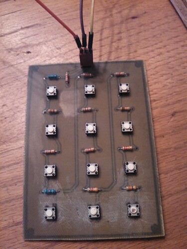
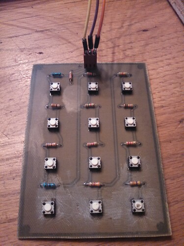
i have attached an eagle design i have made for a 12 button ladder. i have found it to be more reliable than a breadboard and the user can plug i what ever resistor values they want and test values using the 'Button Read' sketch. i have been within 4 points using the PCB and a lot higher spread with breadboard. i hope some will be able to put to use and have better results with their projects. the eagle files do not show but i want to use single machined header pins for the resistor leads and tact buttons soldered to board as they are on a new board to allow changing resistors without getting solder gun out every time. the 5V-output-GND 3 pin can be pulled off and turned to reverse 5V & GND for different values, pulled high/ pulled low.
in the attached pics: labeled according to pin attachment,
orange - 5V
purple - value
yellow - gnd
that being said, i have tested my button board and was able to get 4 readings from each button setup as the 4 different input methods mentioned above for a total of 48 readings from one board.
so... without having to physically reverse 3 pin connector by hand, is there a way to reverse pins through programming or pin assignments?
Button Keypad.sch (161 KB)
Button Keypad.brd (71.4 KB)


