I'm trying to use Piezo electric discs to make an electronic drum.
In many tutorials, Piezo electric disc was directly connected to analog pin. (Only connect a 1MΩ resistor in parallel to the Piezo element)
Reference:
MY QUESTION IS: IS THAT SAFE? CAN RELIABILITY BE GUARANTEED?
I use the oscilloscope to directly test the voltage that can be generated at both ends of the Piezo element, which can probably reach ±10V. In MCU datasheet, Absolute Maximum Ratings of Pin input voltage was GND-0.5V~Vcc+0.5V. (For the Pro Micro I used it was -0.5V~5.5V). The voltage produced by the Piezo electric disc seems to exceed the acceptable range of the analog Pin.
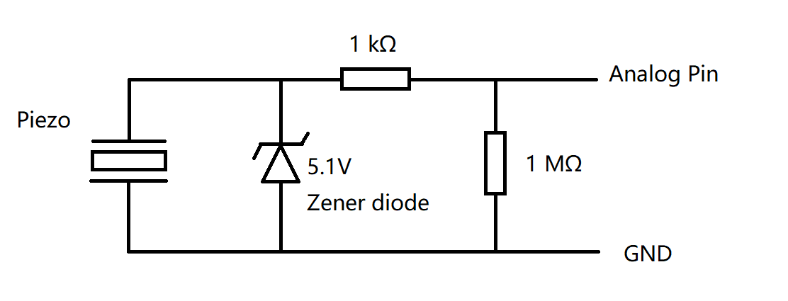
I also see some Piezo Disk Vibration Sensor Module. The schematic looks like this. Additionally, a Zener diode is connected in parallel.
However, the Zener diode will not be switched on until the forward voltage exceeds 0.7V. This means that there may be -0.7V voltage input to the Arduino (Test by oscilloscope saw that this was indeed happening). Is that safe?
I have used my drum for a period of time. And I even hit during Arduino power off. There is no problem. Why? Because the current generated by the Piezo element is too small to destroy the protective diodes in the MCU?
Thanks for reading my broken English. Looking forward to your reply.
No, there are no guarantees. The current produced by small piezo disks is very tiny, and not likely to damage the input protection diode on the port pin.
Any time you connect an analog input pin to something in the real world, you are taking a risk of damage due to induced voltages from external electric fields, or the equipment exceeding the input voltage specification.
Zener diodes won't help, but a 10K series resistor will limit the current through the input protection diode to reasonable values, for input voltages up to 20V or so.
not really. you better protect pin from overcurrent with current limiting resistor not less then 250 Ohn in serie. and flyback diode in parallel to piezo.
Thank you. I'm seriously considering adding a series resistor. I may be inclined to add a few kΩ of resistance to ensure that the current flowing into the analog pin is less than 1mA (at -0.7V input). But I wonder why the Piezo Disk Vibration Sensor Module, which is widely available on the market, has such design risks.
That might be OK for an output pin, where the output fets are conducting,
but that value is almost useless for an input pin.
10k would be a better choice (post#2), and a pair of Schottky clamping diodes.
Leo..
The protection diodes on the IC pins are there for protection against ESD and voltage transients. They were not intended to be used in continuous operation as voltage clamps.
If RELIABILITY is a concern then use external circuitry to limit the voltage
I appreciate your advice! But 5V Schottky diodes seems not easy to get for me. I'm going to change my circuit to this. I think the risk is pretty low like this.
Using an oscilloscope, I found that the Piezo Disk Vibration Sensor Module output voltage is less than 5V. And in theory, greater than 5.5V will activate the protective diode in the MCU. The temperature might have some effect on the Zener diode, but I checked the datasheet and it didn't have much effect. Considering other fluctuations, your suggestion may be sound. But the main thing for me is that I have to buy the 4.7V zener again.
I can't get them either, because they don't exist.
Your circuit won't limit negative spikes from the piezo.
Your circuit won't protect for positive spikes when the Arduino happens to be off.
A clamping circuit consists of two Schottky (low threshold) diodes (1N5819 etc.),
one between pin and ground and one between pin and VCC, both reverse biased.
Google can show you too.
Leo..
Got it! Thank you for your reply! But in this case, for me, the PCB Layout needs to be greatly adjusted.
What I want to know now is: If the large resistance(10kΩ) is connected in parallel. Is the risk already low? (even if the protection diode in the MUC flows through a current of <1mA)
1Megohm must be used in parallel (across the piezo), to ensure voltage returns to zero after a hit.
10k can be used in series (between piezo and Arduino pin) to make it easier on the MCU's built-in clamping diodes (which are unspecified in the datasheet).
Leo..
Sorry, I made a mistake. I meant to say " 10kΩ in series". The MCU's built-in clamping diodes' specifications are really unclear, so I don't know that the maximum current it allows is 0.5mA or 1mA or 20mA...
Some noise appears in the data captured by my analog pin when I don't touch the piezo, even though it is very small (1/1024).
It has been determined that it is related to the connection with Vcc. If my PCB is not connected to Vcc, there will be no such noise.
Do you know how to solve it?
Schottky diodes leak more than normal ones.
You could fix it in software.
rawValue = analogRead(piezoPin);
if (rawValue > 1) {
  // do something
}
What are you going to do with this A/D value.
If you reduce it to 0-255 or 0-127 for MiDi, then that noise will disappear. midiValue = analogRead(piezoPin) >> 3; // 10-bit to 7-bit
Leo..