Here is a code-version with additional debug-macros and additional serial printing of the bytes that you send towards the sensor and the bytes you receive from the sensor.
This will help analyse what is going on
// MACRO-START * MACRO-START * MACRO-START * MACRO-START * MACRO-START * MACRO-START *
// a detailed explanation how these macros work is given in this tutorial
// https://forum.arduino.cc/t/comfortable-serial-debug-output-short-to-write-fixed-text-name-and-content-of-any-variable-code-example/888298
#define dbg(myFixedText, variableName) \
Serial.print( F(#myFixedText " " #variableName"=") ); \
Serial.println(variableName);
#define dbgi(myFixedText, variableName,timeInterval) \
{ \
static unsigned long intervalStartTime; \
if ( millis() - intervalStartTime >= timeInterval ){ \
intervalStartTime = millis(); \
Serial.print( F(#myFixedText " " #variableName"=") ); \
Serial.println(variableName); \
} \
}
#define dbgc(myFixedText, variableName) \
{ \
static long lastState; \
if ( lastState != variableName ){ \
Serial.print( F(#myFixedText " " #variableName" changed from ") ); \
Serial.print(lastState); \
Serial.print( F(" to ") ); \
Serial.println(variableName); \
lastState = variableName; \
} \
}
#define dbgcf(myFixedText, variableName) \
{ \
static float lastState; \
if ( lastState != variableName ){ \
Serial.print( F(#myFixedText " " #variableName" changed from ") ); \
Serial.print(lastState); \
Serial.print( F(" to ") ); \
Serial.println(variableName); \
lastState = variableName; \
} \
}
// MACRO-END * MACRO-END * MACRO-END * MACRO-END * MACRO-END * MACRO-END * MACRO-END *
unsigned long MyTestTimer = 0; // Timer-variables MUST be of type unsigned long
const byte OnBoard_LED = 13;
/*
BlinkHeartBeatLED(OnBoard_LED,250);
if ( TimePeriodIsOver(MyTestTimer,1000) ) {
}
*/
#include <Wire.h>
#include <LiquidCrystal_I2C.h>
#include <SoftwareSerial.h>
// Define LCD address and dimensions
LiquidCrystal_I2C lcd(0x27, 16, 2); // Adjust 0x27 to your LCD's I2C address if necessary
#define RE 7
#define DE 6
#define RELAY_PIN 5 // Pin connected to the relay module controlling the water pump
const uint32_t TIMEOUT = 2000UL; // Increased timeout for sensor response
const byte moist[] = {0x01, 0x03, 0x00, 0x00, 0x00, 0x01, 0x84, 0x0A};
const byte temp[] = {0x01, 0x03, 0x00, 0x01, 0x00, 0x01, 0xD5, 0xCA};
const byte PH[] = {0x01, 0x03, 0x00, 0x03, 0x00, 0x01, 0x74, 0x0A};
const float MOISTURE_THRESHOLD = 20.0; // Moisture level below which the pump will turn on
byte values[11];
SoftwareSerial mod(2, 3); // Rx pin, Tx pin
void setup() {
Serial.begin(4800); // Match with the sensor's baud rate
Serial.println("Setup-Start");
PrintFileNameDateTime();
mod.begin(4800);
pinMode(RE, OUTPUT);
pinMode(DE, OUTPUT);
pinMode(RELAY_PIN, OUTPUT);
lcd.init(); // Initialize the LCD
lcd.backlight(); // Turn on the backlight
digitalWrite(RELAY_PIN, LOW); // Ensure pump is off at startup
lcd.setCursor(0, 0);
lcd.print("Initializing...");
delay(1000);
}
void loop() {
// Moisture reading
lcd.clear();
lcd.setCursor(0, 0);
lcd.print("Moisture:");
float moistureValue = readSensor(moist) * 0.1;
lcd.setCursor(0, 1);
lcd.print(moistureValue);
lcd.print(" %");
delay(2000); // Display for 2 seconds
// Control water pump based on moisture level
if (moistureValue < MOISTURE_THRESHOLD) {
digitalWrite(RELAY_PIN, LOW); // Turn pump ON
lcd.clear();
lcd.setCursor(0, 0);
lcd.print("Pump ON");
}
else {
digitalWrite(RELAY_PIN, HIGH); // Turn pump OFF
lcd.clear();
lcd.setCursor(0, 0);
lcd.print("Pump OFF");
}
delay(2000); // Display for 2 seconds
// Temperature reading
lcd.clear();
lcd.setCursor(0, 0);
lcd.print("Temperature:");
float temperatureValue = readSensor(temp) * 0.1;
lcd.setCursor(0, 1);
lcd.print(temperatureValue);
lcd.print(" C");
delay(2000); // Display for 2 seconds
// pH reading
lcd.clear();
lcd.setCursor(0, 0);
lcd.print("pH Level:");
float phValue = readSensor(PH) * 0.1;
lcd.setCursor(0, 1);
lcd.print(phValue);
delay(2000); // Display for 2 seconds
}
int16_t readSensor(const byte* command) {
uint32_t startTime = 0;
uint8_t byteCount = 0;
memset(values, 0, sizeof(values)); // Clear previous data
digitalWrite(DE, HIGH);
digitalWrite(RE, HIGH);
delay(10);
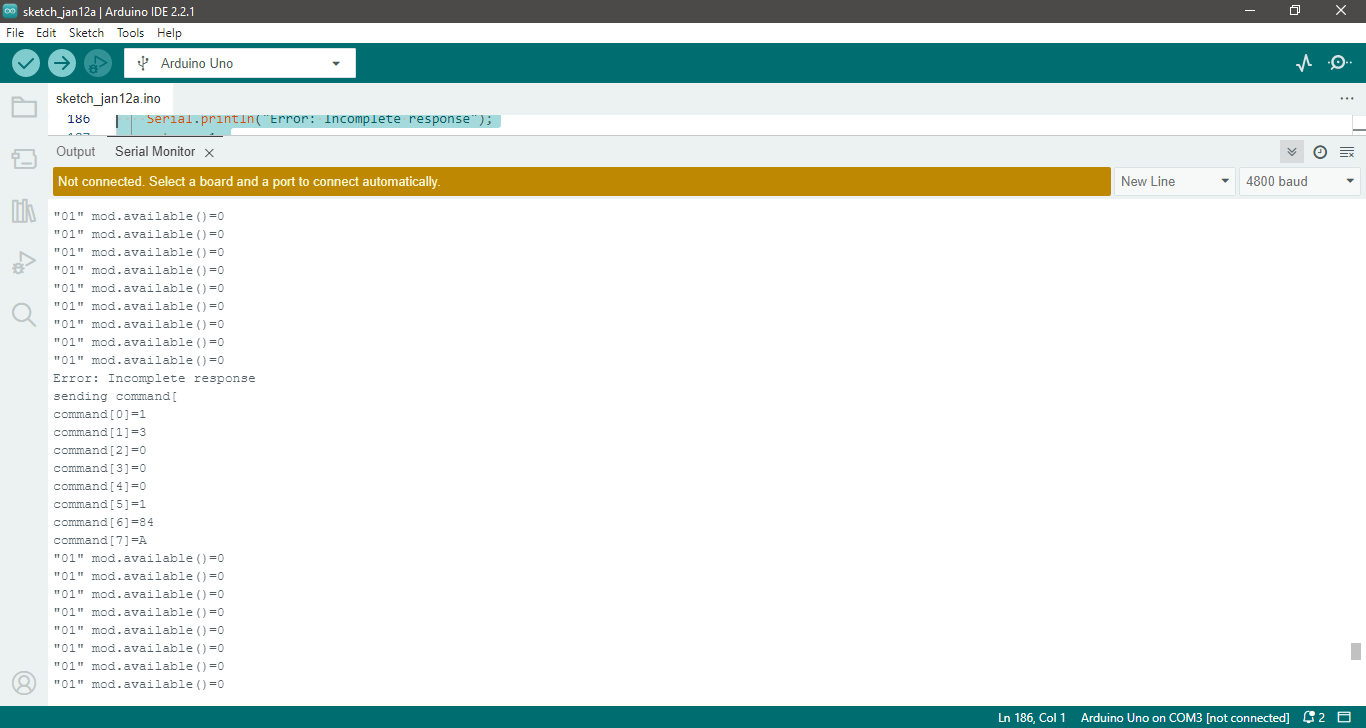
Serial.println("sending command[");
for (byte i = 0; i < 8; i++) {
// print each and every byte that is sent
Serial.print("command[");
Serial.print(i);
Serial.print("]=");
Serial.println(command[i], HEX);
}
mod.write(command, 8); // Send command (8 bytes)
mod.flush();
digitalWrite(DE, LOW);
digitalWrite(RE, LOW);
delay(100); // added this delay to give the sensor time to send his answer
startTime = millis();
while (millis() - startTime <= TIMEOUT) {
// print number of bytes received
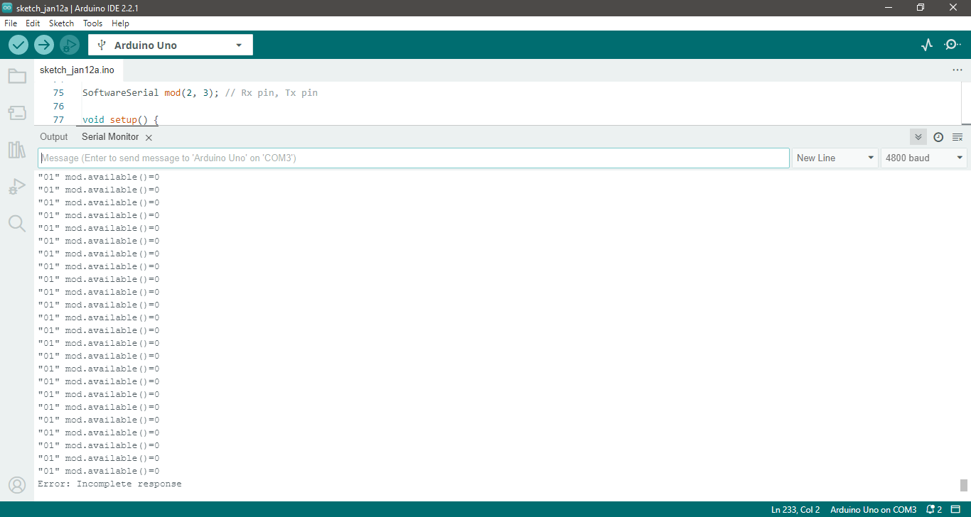
dbg("01", mod.available());
if (mod.available() && byteCount < sizeof(values)) {
values[byteCount] = mod.read();
// print each and every received byte
Serial.print("values[");
Serial.print(byteCount);
Serial.print("]=");
Serial.println(values[byteCount], HEX);
byteCount++;
}
}
// Check if response is valid
if (byteCount < 7) {
Serial.println("Error: Incomplete response");
return -1;
}
// Combine high and low bytes of data
return (int16_t)(values[3] << 8 | values[4]);
}
void printHexByte(byte b) {
Serial.print((b >> 4) & 0xF, HEX);
Serial.print(b & 0xF, HEX);
Serial.print(' ');
}
// helper-functions
void PrintFileNameDateTime() {
Serial.println( F("Code running comes from file ") );
Serial.println( F(__FILE__) );
Serial.print( F(" compiled ") );
Serial.print( F(__DATE__) );
Serial.print( F(" ") );
Serial.println( F(__TIME__) );
}
// easy to use helper-function for non-blocking timing
// explanation see here
// https://forum.arduino.cc/t/example-code-for-timing-based-on-millis-easier-to-understand-through-the-use-of-example-numbers-avoiding-delay/974017
boolean TimePeriodIsOver (unsigned long &startOfPeriod, unsigned long TimePeriod) {
unsigned long currentMillis = millis();
if ( currentMillis - startOfPeriod >= TimePeriod ) {
// more time than TimePeriod has elapsed since last time if-condition was true
startOfPeriod = currentMillis; // a new period starts right here so set new starttime
return true;
}
else return false; // actual TimePeriod is NOT yet over
}
void BlinkHeartBeatLED(int IO_Pin, int BlinkPeriod) {
static unsigned long MyBlinkTimer;
pinMode(IO_Pin, OUTPUT);
if ( TimePeriodIsOver(MyBlinkTimer, BlinkPeriod) ) {
digitalWrite(IO_Pin, !digitalRead(IO_Pin) );
}
}
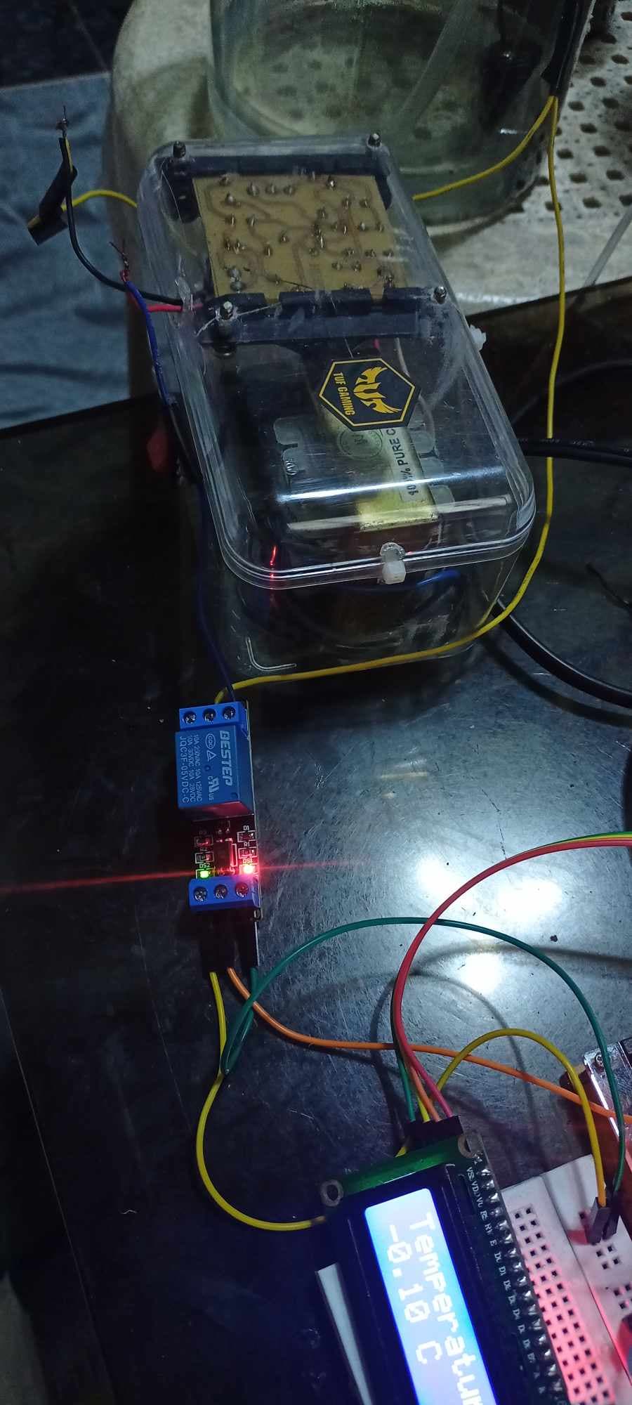
you have written that you are powering the
- LCD-display
- relay
- RS485-module
all from the 5V-pin of the Arduino.