Can't get TFT SPI 2.8" Display to work with Arduino Mega 2560 Pro

I have followed each wire back and forth at least three times now. I'll recheck though. I'll copy-paste the code next time. I just was not sure that the library was being read correctly since it was not colored. My soldered joints are not very good. That could be why my level shifter may not be working properly. I've only ever soldered around 20 pins.

It is possible that it is the level shifter that is faulty. I was measuring negligible voltage when I used a voltmeter to test some of the shifted connections. Would it be possible to make voltage dividers with different resistors? I only have 6 1k resistors, 9 10k resistors, and a few 220R resistors (From my very first arduino kit) As such:
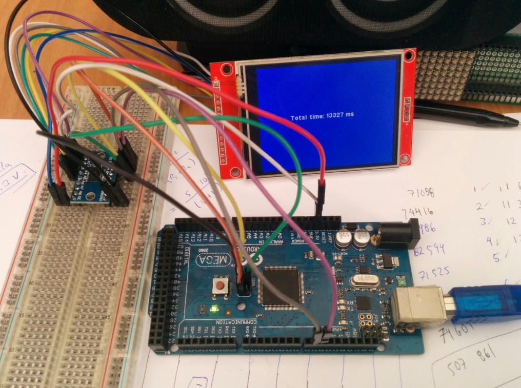
(Please assume that the green wires are to connect to an SPI pin.) Each voltage divider circuit mimics the one in the previous photos.

Why did you not say?

You can make 3 voltage dividers with 1k0+1k0 e.g. CS, MOSI, SCK
You can make 4 voltage dividers with 10k+10k e.g. DC, RST
Omit MISO

Yes, I know this turns 5V into 2.5V but 2.5V will be fine for 3.3V logic high.

Follow my scheme in #3. It means you have very few trailing wires.

I am sure that your TXB0104 is fine. The resistors will be easier to mount on the breadboard. i.e. less wires.

Oh, buy some 470R, 1k0, 4k7, 10k resistors and some 100nF capacitors. From a local Ebay shop.
If you are unsure of your soldering, post a photo. (or just follow some soldering tutorial videos)

David.

You're right. My voltage shifter is fine. It is my D50 (MISO) D49 (RST) pin that seems to output negligible voltage unless it is really like that? However, I can measure 2.5-3V on the MOSI and SCK connections.
Should I switch them to their ICSP pins? If so, may I ask how to assign the pins?

If I assign MISO to the D50 pin as such:

#define TFT_MISO 50

How do I define it to the MISO pin here:

Posting a photo of the solder on the TXB0104.
This was my first solder in 2 years and my last one was for a grade 10 project.
I am concerned that my soldering may have damaged the shifter.

MOSI, SCK, MISO, ... are the same 51, 52, 50 as the next-door header
CS is only on the next-door header.

I am clutching at straws. I am sure that the Mega2560_Pro designer has marked the header pins correctly.

If the header pins were not professionally soldered, I would examine them closely.

Your soldering is "not too bad". Re-heat each joint with your soldering iron. Each joint should look smooth, clean and shiny. Look at Tutorial videos.

Re-flow the Mega2560_Pro headers if they look like the TXB0104.

No, you can't harm the TXS0104 chip. The heat from the soldering iron goes to the header pins. It never melts the TXS0104 solder.

David.

The ICSP header pins do not need to be defined. The Reset pin of the TFT can be connected to 3.3V, it is not necessary to use it in the library constructor. As David pointed out, the MISO pin of the TFT does not need to be connected.

This leaves you only 4 pins to control your TFT: SCK, MOSI, CD and CS, you don't need to build those two extra voltage dividers.

The constructor would then be:

#define TFT_DC 9
#define TFT_CS 10
ILI9341_due tft = ILI9341_due(TFT_CS, TFT_DC);

TXS0108E on MEGA


Library: ILI9341_due or ILI9341_kbv

Important:
Remember to click the reset button of your Arduino MEGA, these screens are something special in 5V AVR environments, they leave the "SPI pins floating", so when you disconnect and connect the MEGA, you must apply a manual reset.

This is why I migrated to native 3.3V platforms.

PD:
David by the way your library ILI9341_kbv works on teensy 4 !!!

The ID = 0x180 is wrong. You need to either reduce the SPI speed or add some delays when reading registers.

Writing to registers is much faster. The ILI9341 datasheet says 10MHz e.g.

18.3.4 Display Serial Interface Timing Characteristics (4-line SPI system)
twc Serial clock cycle (Write) 100 - ns

But in practice Marek uses 42MHz on the Due.
Bodmer uses 40MHz on ESP32 (default to a safer 27MHz for most controllers)

Whereas the datasheet timing limits are pretty accurate for the Parallel interfaces, SPI seems to be very conservative.

David.

It was just an experiment since I have a teensy 4 on hand with a 1.8 "ST7735-touch. A while ago I was experimenting with the ILI9341 screens, so the head is 100% functional. I saw that the ILI9341_kbv library compiled well and only the I connected lol.

The MISO pin is not connected, is that why it reads the wrong ID?

By the way, I have countless questions with that library:
Is it possible to use the spitftbitmap example from adafruit's old ILI9340 library?
How is the pushColors instruction that is defined in the ILI9341_kbv library used?

Maybe this is the key to load a bmp file from SDIO reader of the teensy 4 or 4.1, to the ILI9341 TFT.

Inside of the spitftbitmap.ino, the pushColor instruction is used like this:

            // Convert pixel from BMP to TFT format, push to display
            b = sdbuffer[buffidx++];
            g = sdbuffer[buffidx++];
            r = sdbuffer[buffidx++];
            tft.pushColor(tft.Color565(r,g,b));

So the question is: Is the pushColors (ILI9341_kbv lib) an equivalent of pushColor (ILI9340 lib) instruction?

The original Adafruit_TFTLCD, Adafruit_ILI9341, Adafruit_ST7735 libraries (circa 2014) all worked with :

	void     setAddrWindow(int16_t x, int16_t y, int16_t x1, int16_t y1);
	void     pushColors(uint16_t *block, int16_t n, bool first);

i.e. setAddrWindow() used x1, y1 and pushColors() had a flag to indicate first

subsequently Adafruit silently changed the argument style to a more intuitive:

	void     setAddrWindow(int16_t x, int16_t y, uint16_t w, uint16_t h);

This means that the old 2014 spitftbitmap.ino example requires adjusting to w, h instead of x1, y1

Actually some Adafruit libraries had pushColors() and some only had pushColor()
The current setAddrWindow(x, y, w, h) sets the window and issues a RAMWR() command.
Which means that you can use as many pushColor() calls without worrying about first

You can implement pushColor(uint16_t pixel) by calling pushColors(&pixel, 1, first)

In hindsight, I should really deprecate my setAddrWindow(x, y, x1, y1) and invent a new setRectWindow(x, y, w, h) method.

Perhaps a pushRect(x, y, w, h, pixels) method is the best approach.
For example, rendering a .BMP image bottom upwards is easier.

Simple answer: Adafruit_GFX has had intuitive methods from Day One.
Some dependent hardware libraries have not always chosen the best method implementations.
I should have changed my library style(s) immediately that Adafruit did. In which case there would not have been as many Users as today.

Or perhaps Adafruit should have changed the setAddrWindow() name when they changed the arguments.

David.

I tried TFTLCDyg's same setup, using the ICSP pins and pin 9 for DC, pin 10 for CS. It is very possible that I have a rogue wire since the information is probably not being transmitted properly—the display is flickering. I attached a gif for reference. It's not very evident in the gif but it was definitely flickering. I did note that it flickered more (had darker variations) when using the TFT_ILI9341 library instead of the Adafruit_ILI9341.

ezgif.com-gif-maker.gif

ezgif.com-gif-maker.gif

I disassembled the TFT to be able to do the BMP image load tests from the teensy 4 SDIO reader. I have been looking for 10K resistors than normal, but I did not find enough.

Forget the level converter for a moment, we better go to wiring with resistive voltage dividers.

With the photo in mind, consider for each TFT control line, this sequence:

The wire that comes from the Arduino MEGA is connected to one of the terminals of the small resistor. The other terminal of this resistor is connected to the TFT pin. Join here the terminal of the major resistor; the other terminal of this resistor goes to ground.

David I went a little further in time, to my surprise with some minor adjustments, you can use the current SD library of the most recent teensyduino (with touches of SdFat beta) and I have been able to use the ILI9341_kbv library to load BMP images from the SDIO reader of the teensy 4.

The library from which I took the example is Adafruit's TFTLCD, which allows to connect the first red shields with the ILI9325 chip. It has the pushColors statement with the structure that is present in ILI9341_kbv:

tft.pushColors(lcdbuffer, lcdidx, first);

MCU: Teensy 4 (FCPU=150 MHz), ILI9341 SPI 3.2"
ILI9341_kbv library test


ILI9341_t3 library test

Foff.zip (163 KB)

ILI9341_kbv_spitftbitmap.ino (7.24 KB)

ILI9341_t3_spitftbitmap.ino (8.02 KB)

Thank you for the information about the SD library, I'll attempt to use it once I've got the display running.
I've received my TCS0108e logic shifter, connected everything but I'm still banging my head trying to get the display to work. Please go over the attachments I sent of the setup. I'll restate the connections and wire color scheme and code:
TFT_DC 9 //violet
TFT_CS 10 //green
TFT_MOSI 51 //white
TFT_CLK 52 //brown
TFT_RST 8 //red
TFT_MISO 50 //orange

First few lines of the Adafruit graphicstest example:

#include <SPI.h>
#include <Adafruit_GFX.h>
#include <Adafruit_ILI9341.h>

#define TFT_DC 9 //violet
#define TFT_CS 10 //green
#define TFT_RST 8 //red

Adafruit_ILI9341 tft = Adafruit_ILI9341(TFT_CS, TFT_DC, TFT_RST);

void setup() {
  Serial.begin(9600);
  Serial.println("ILI9341 Test!"); 
 
  tft.begin();

At this point, I really do apologize for taking so much of your time and I'm really grateful that you guys are helping me with getting the display to work for my setup.

two more photos (file size was too large to fit in the first)

Your soldering is "not too bad". Re-heat each joint with your soldering iron. Each joint should look smooth, clean and shiny. Look at Tutorial videos.

Re-flow the Mega2560_Pro headers if they look like the TXB0104.

You have never answered. Were the headers professionally soldered on the Mega2560_Pro ?
Have you re-flowed the solder on the TXB0104 and TCS0108e modules ?

Your wiring "looks" correct. But one single loose/bad contact can ruin everything.

David.

Right, sorry. The soldering for the mega was done by me and was reflowed. It looks the same as the soldering on the level shifter, I've only just soldered the TXS0108E a few hours ago.

Wow, wow, you got a TXS0108e, XD. The pin called OE, located at the end of port A, must be connected to 3.3V

Attached photos of my breadboard running Adafruit's graphictest.ino (ILI9341 Library) using TXS0801 bi-directional level shifter module with Arduino Mega. Mega: RST pin 8, D/C pin 9, CS pin 10, MOSI pin 51, SCK pin 52.

Thank you, borland, for your photos and connections. I trick mimicking your setup my mega 2560 pro but I still could not get it to work.
TFTLCDCyg, I connected OE to 3.3v but still could not get the display to work.
I was afraid that it was the board itself that may have some issues but when I tried connecting the display to an arduino uno, I still could not get it to function. I've posted photos of it below.

TFT_DC 9 //violet
TFT_CS 10 //green
TFT_MOSI 10 //white
TFT_CLK 13 //brown
TFT_RST 8 //red
TFT_MISO 12 //orange

#include "SPI.h"
#include "Adafruit_GFX.h"
#include "Adafruit_ILI9341.h"

#define TFT_DC 9
#define TFT_CS 10
#define TFT_RST 8

Adafruit_ILI9341 tft = Adafruit_ILI9341(TFT_CS, TFT_DC, TFT_RST);

Could it be the TFT that is broken? I may have supplied the wrong voltage, 5v, when I first tried it out.

IMG_3830.jpg

IMG_3830.jpg

For Arduino Uno board...
MOSI is pin 11 (or pin 4 of ICSP )
MISO is pin 12 (or pin 1 of ICSP )

See this Arduino web page: SPI Connections