Changing from VIN to 5V to test

Hi

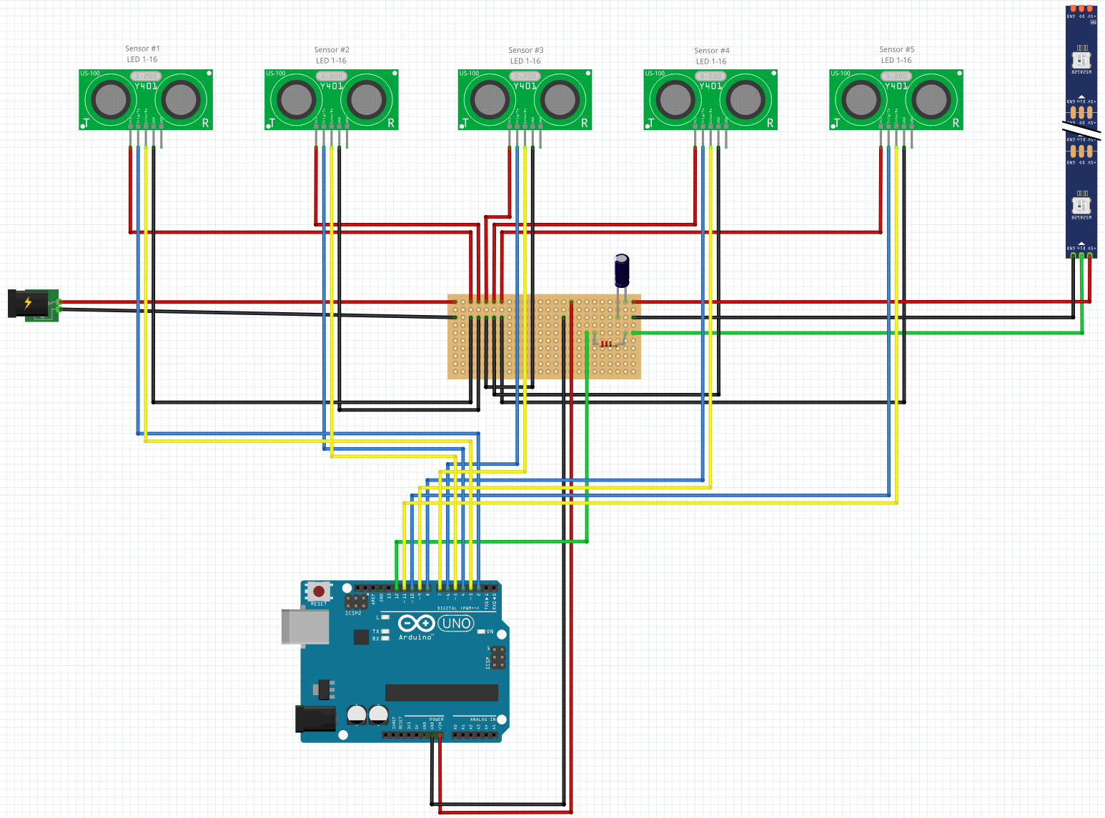
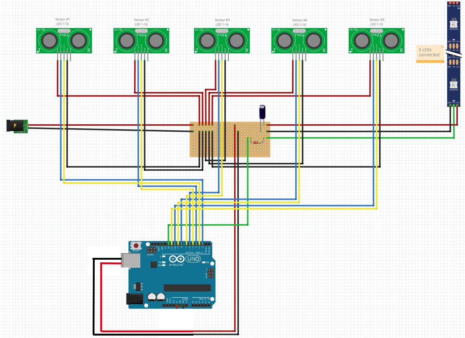
I have made this diagram for a project. I wont to be able to test and programme it, so I wont to create a "test mode". I have tried to make a change to the diagram where I connect it to a PC.

Normal mode: 5V to bread board and Arduino powered with VIN + 75 LED

Test mode: Arudino powered with USB from PC and 5V to bread board from Arduino + 5 LED

Is the above possible or should I do something else to be able to test my code on the final project?

Thanks in advance.

/Henrik

If the barrel connector on the left is connected to 5V, then the first diagram won't work and no point in considering the second diagram.

The UNO can only deliver so much power OUT of the 5V pin regardless of the power source. It can deliver less if the input power is less however.
For that many LEDs use a separate power supply, and use a MOSFET that is controlled from the UNO to feed power to all the LEDs.

Why won't the first diagram work?

It is a addressable LED and as far as I can read, they use 5V.

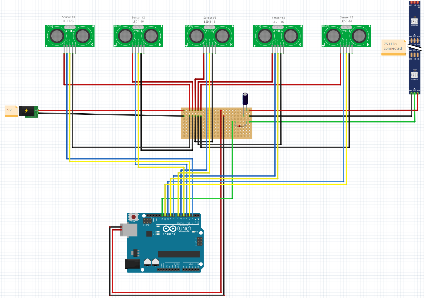
But as I wrote, the second diagram is only powering 5 LEDs - so the test mode only powers 5 LEDs and normal mode is 75 LEDs. I have two different strips, so I can connect the 5 LEDs when testing.

Vin needs to be greater than 7V and less than or equal to 12V

2nd is fine.

That will fry the UNO. Read UNO datasheet to determine max current. Now multiple each LEDs current by 75. Solve.

For testing, if the Uno is powered by USB then you should not have anything connected to 5V or Vin.

See the section on Power

Thanks for both of your input.

Would the below be fine?

Production: Two power inputs (5V and USB power adaptor) | no plus-connection between bread board and Arduino; only negative | 75 x WS2812B LEDs

The power to arduino are done using something like this (it is an Arduino Nano 3.0 (couldn't find a drawing of it in Fritzing):

Test: One power input (USB from PC) | plus-connection from Arudino 5V to bread board | 5 x WS2812B LEDs

The first diagram is OK.
The second is not.
Please read the section on Power in the link I provided in post #9

I have updated both diagrams - will you take another look?

Thanks again.

It depends on the LEDs. What are they?

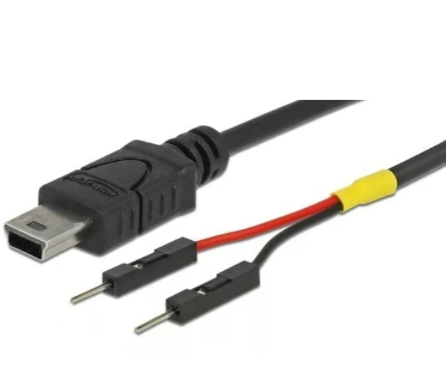
  • If you power the Arduino UNO using the 5v Arduino pin, you should be careful.
    There is the possibility the external 5v can back feed to the PC/Laptop if they are powered down.
    If you connect the 5v external power supply to the Arduino using the USB cable rather than the 5v pin, this won’t be an issue.

It is a WS2812B LED stip, 5V - diagram discription updated in post #10

I have updated the diagrams in post #10 - is this what you mean?

Then the two original diagrams in post #10 (before you changed them) are/ were OK.

Now they are not OK.

Again, thanks for both of your time.

I have tried to incoporate both of your input in updated drawings.

You will find that does not exist.
That is why I did not suggest it.

I am not sure I understand - wouldn't this do it: