Hi all, I was hoping for some guidance on how to safely make a common ground between 300 WS2812b LEDs (18A) and a fairly sensitive audio analyzing circuit that is connected to the Arduino.
I have a 5V 20A PSU which I will use 10 AWG wire (for 5V and GND) directly feeding the LEDs.
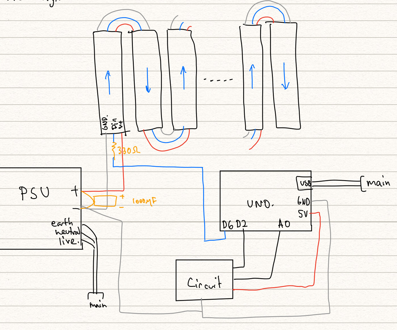
From a suggestion I found through this link, I believe the solution may be as simple as running the ground wire from the Arduino, to the breadboard where the circuit is located, and down to the external PSU where it finally connects to the same GND terminal as the LED GND wire.
I've included a diagram of my setup below, and I was wondering:
-Is this a safe way to create a common ground where my Arduino and circuit will not be damaged?
-Is there any major potential to mess with the accuracy of the audio analyzing circuit? I vaguely recall reading somewhere that high voltage in close proximity could mess with frequency analysis, but I may be sorely mistaken.
That concept appears to be fine.
You could also run each Gnd wire for the circuit and the Arduino individually to the power supply.
If the two will located close to each other, what you have is fine.
You're also going to need to connect +5/Gnd to the strips in parallel. You'll see lots of voltage drop down the line as the traces in the LED strips heat up from 20A going thru the strips.
The data is fine going strip to strip, each chip buffers the signal and passes it along. The power & gnd need to be in parallel to each other.
CrossRoads:
That concept appears to be fine.
You could also run each Gnd wire for the circuit and the Arduino individually to the power supply.
If the two will located close to each other, what you have is fine.
Thank you for the clarification. Saved my sanity, I have been slaving away at this design for a while lol
CrossRoads:
You're also going to need to connect +5/Gnd to the strips in parallel.
I'm not quite sure what you mean by this, do you mean use the second set of + - terminals on the PSU and connect it to the other end of the LED strip?
CrossRoads:
The data is fine going strip to strip, each chip buffers the signal and passes it along. The power & gnd need to be in parallel to each other.
Like this on the strips?
Yes. If larger Power/Gnd wire is too awkward to connect to all strips, then use smaller gage wire and just connect up say 3 or 4 strips to one set of wires, and have multiple wires going from the supply to the groups of 3 or 4.
Still all connected in parallel, but just in parallel at the power supply instead.
CrossRoads:
Yes. If larger Power/Gnd wire is too awkward to connect to all strips, then use smaller gage wire and just connect up say 3 or 4 strips to one set of wires, and have multiple wires going from the supply to the groups of 3 or 4.
Still all connected in parallel, but just in parallel at the power supply instead.
Got it, I'll try to implement the design in reply 4 as it will minimize the amount of wires going down to the PSU (Probably going to mount LED strips on a wall with PSU sitting on the ground). I ordered 14 AWG wire for PSU to LED strips - I've never soldered before, so would you say they are too thick to solder to the NeoPixel copper pads and to use as the ground and voltage connections in between strips?
I ordered 22AWG wire for the data line and the Arduino-breadboard-ground connection.
You don't say which LED strips you are using, but what is the max current for each strip? Just run power wires big enough to power each strip from the Power Supply.