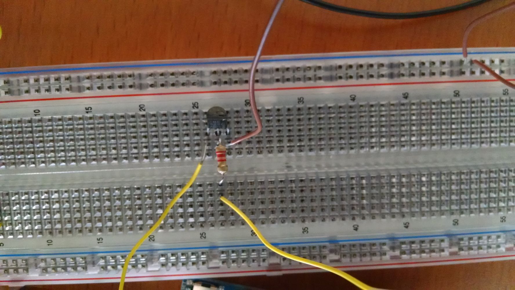
Here's the wiring with the BC547.
Hi,

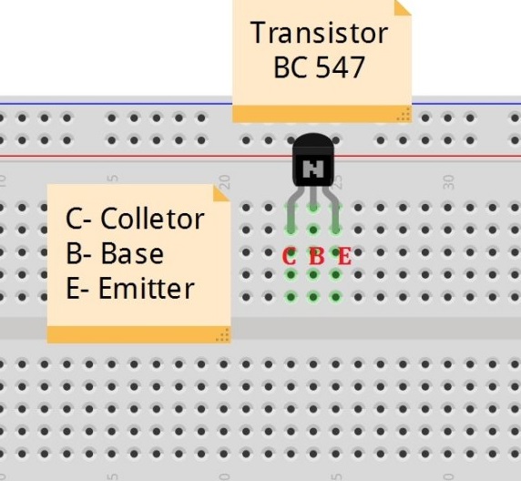
COLLECTOR on the left, to solenoid neg, EMITTER on the right to gnd, BASE in the middle.
Cannot see where you wires go, can you get arduino and solenoid closer together and in the same frame please.
Tom... ![]()
The picture:-
(Again, right-click and "View Image" or similar for full-size.)
dzaks, after attaching an image and posting, you can copy the URL of the image, then edit the post and place that URL within [img]image tags[/img] using the "Insert an image" button in the edit window.
It doesn't show where the wires actually go. (Tom also said this as I was typing.)
Still, assuming the left-hand wire goes to the negative side of the solenoid, the connections look fine to me. I have no idea why it won't turn off.
Wait, is that really a BC547? It looks like the label says BC548. A BC548 is only rated for an absolute maximum of 30V. A BC547 is rated for 45V, that's why I suggested it.
Is it just my eyes?
Hi,
I'd say BC548 as well.
I don't have my CSI magical image enhancement package open so I can't supply a hi-res cleaned up picture. lol
Tom... ![]()
Wow, I have no idea how you guys caught that, but yes, it was a 548; I didn't realize those were also lying here. I'm impressed with your CSI magic : ) But I have replaced it now with the BC547.
And yes, as OldSteve assumed correctly, the left side yellow wire is going to the negative terminal of the solenoid, the resistor wire is going to the Arduino pin 4, and the brown wire is going to ground.
The COLLECTOR voltage relative to ground is also pretty constant at 7.1 V, even when the base voltage drops from 4.9 V to ~ 5 mV.
dzaks:
Wow, I have no idea how you guys caught that, but yes, it was a 548; I didn't realize those were also lying here. I'm impressed with your CSI magic : ) But I have replaced it now with the BC547.And yes, as OldSteve assumed correctly, the left side yellow wire is going to the negative terminal of the solenoid, the resistor wire is going to the Arduino pin 4, and the brown wire is going to ground.
The COLLECTOR voltage relative to ground is also pretty constant at 7.1 V, even when the base voltage drops from 4.9 V to ~ 5 mV.
It just gets weirder and weirder. If Tom or I were there, armed with a multimeter, this would be sorted out in <5 minutes.
7.1V? And when providing 5V from the Arduino through the base resistor, the actual base of the transistor should never be at 4.9V. It shouldn't get higher than about 0.7V!
This has me bamboozled. Something simple is seriously wrong here. Something that we can't see in the pics.
All I can think of is a short inside the breadboard.
Anyway, I'm out of suggestions, so will have to bow out at this stage.
Edit: Are you absolutely positive that the BC547 is not already dead? I'd personally be testing it in a separate LED circuit at this stage, as well as testing for breadboard shorts. Some breadboards have an aluminium backing, and maybe the component legs are going right through, shorting on the aluminium.
Hi,
What is the gnd to emitter voltage in ON and OFF modes?
Thanks.. Tom... ![]()
TomGeorge:
Hi,
What is the gnd to emitter voltage in ON and OFF modes?Thanks.. Tom...
You might be onto something Tom. The new symptoms sound like the emitter is rising above ground.
Mind you, that hasn't always been the problem. With the MJE3055:-
- GND to transistor EMITTER: 1.1 mV (~0 V)
(And the solenoid was 'on'.)
Hi,
What is the resistance of your solenoid, measure in both directions please.
Tom... ![]()
Hi Tom,
The solenoid looks to have a 1.58 kOhm resistance in both directions.
And the emitter appears to be identical to ground throughout several ON/OFF cycles, at about 0.8 mV above ground.
dzaks:
And the emitter appears to be identical to ground throughout several ON/OFF cycles,
So it's now turning on and off?
Hi,
We need a photo with everything in the picture, the protoboard, the arduino and the solenoid so we can see all your wiring, also show your power supply.
Thanks... Tom... ![]()
OldSteve: sorry, that was misleading - I meant the out pin cycle from the arduino
here are the photos, hopefully it is clear - let me know if anything is unclear or needs labeling. The only change from my previous comments is that I took out one of the 9v DC batteries to see if it would make a difference.


Hi,
Thanks for the pictures.
If you pull the transistor out of the protoboard, and operate the circuit does the solenoid switch OFF.
If you leave the transistor in and pull out the base resistor, and operate the circuit does the solenoid switch OFF.
Does your DMM have a DIODE test function?
Thanks. Tom... ![]()
Going back to bed, its 3:12am. ![]()
TomGeorge:
Going back to bed, its 3:12am.
So you're here in Oz too, Tom. (In my time zone, your reply is also marked 3:12.)
Hi, Steve, yup, Central Victoria, Gold Fields.
If the OP has DMM with diode test,, will get him to mount the transistor on its own on the protoboard and check the diode junctions.
Tom... ![]()
Just having lunch at work.
TomGeorge:
Hi, Steve, yup, Central Victoria, Gold Fields.
I'm an ex-Victorian, now living in Nowra NSW. My grand-parents had a farm near you, in Talbot, (South of Maryborough). I spent all of my school holidays there, (45+ years ago).
If the OP has DMM with diode test, will get him to mount the transistor on its own on the protoboard and check the diode junctions.
Two transistors in a row. This is quite a puzzle.
Sorry for the delay, I was out sick yesterday.
Anyway, pulling out the transistor does turn the solenoid OFF. Pulling the resistor out does not turn the solenoid OFF.
I am not sure the DMM I am currently using has a diode test function, but I can look around and see if the other ones do.
Hi,
The DMM will have a DIODE symbol on the selector.

Like this one between Ohms and mA.
If you place you transistor in the protoboard but not connected to any other components.
Then using DMM in diode mode;
- With Red and Black probes not connected, record DMM display.
- Connect Red to Black probe, record DMM reading.
- Place Red probe to C lead and Black probe to E lead, record DMM reading.
- Place Black probe to C lead and Red probe to E lead, record DMM reading.
Thanks.. Tom... ![]()
So
- DMM = .0L
- DMM = 0.000 V
- DMM = .0L
- DMM = .0L
If it makes a difference, checking the BASE to EMITTER and BASE to COLLECTOR in DIODE test mode gave a value of about 0.66 V for both.
I also repeated all these checks on a previously unopened, identical BC547, and got the same results.